Nissan X-Trail 32. Manual - part 1091


  Главная      Nissan     Nissan X-Trail 32 - Service Manual


поиск по сайту            


содержание   ..  1089  1090  1091  1092   ..


Nissan X-Trail 32. Manual - part 1091


CYLINDER BLOCK

EM-261

< UNIT DISASSEMBLY AND ASSEMBLY >

[QR25DE]

C

D

E

F

G

H

I

J

K

L

M

A

EM

N

P

O

• If it exceeds the limit, replace piston and piston pin assembly and/or cylinder block. Refer to 

EM-280,

"Cylinder Block"

.

Re-boring Cylinder Bore

1.

Cylinder bore size is determined by adding piston to cylinder bore clearance to piston skirt diameter.

2.

Install lower cylinder block, and tighten mounting bolts to the specified torque. Otherwise, cylinder bores
may be distorted in final assembly. Refer to 

EM-248, "Disassembly and Assembly"

 for the tightening pro-

cedure.

3.

Cut cylinder bores.
NOTE:
• When any cylinder needs boring, all other cylinders must also be bored.
• Do not cut too much out of cylinder bore at a time. Cut only 0.05 mm (0.0020 in) or so in diameter at a

time.

4.

Hone cylinders to obtain the specified piston to cylinder bore clearance.

5.

Measure the finished cylinder bore for out-of-round and taper.
NOTE:
Measurement should be done after cylinder bore cools down.

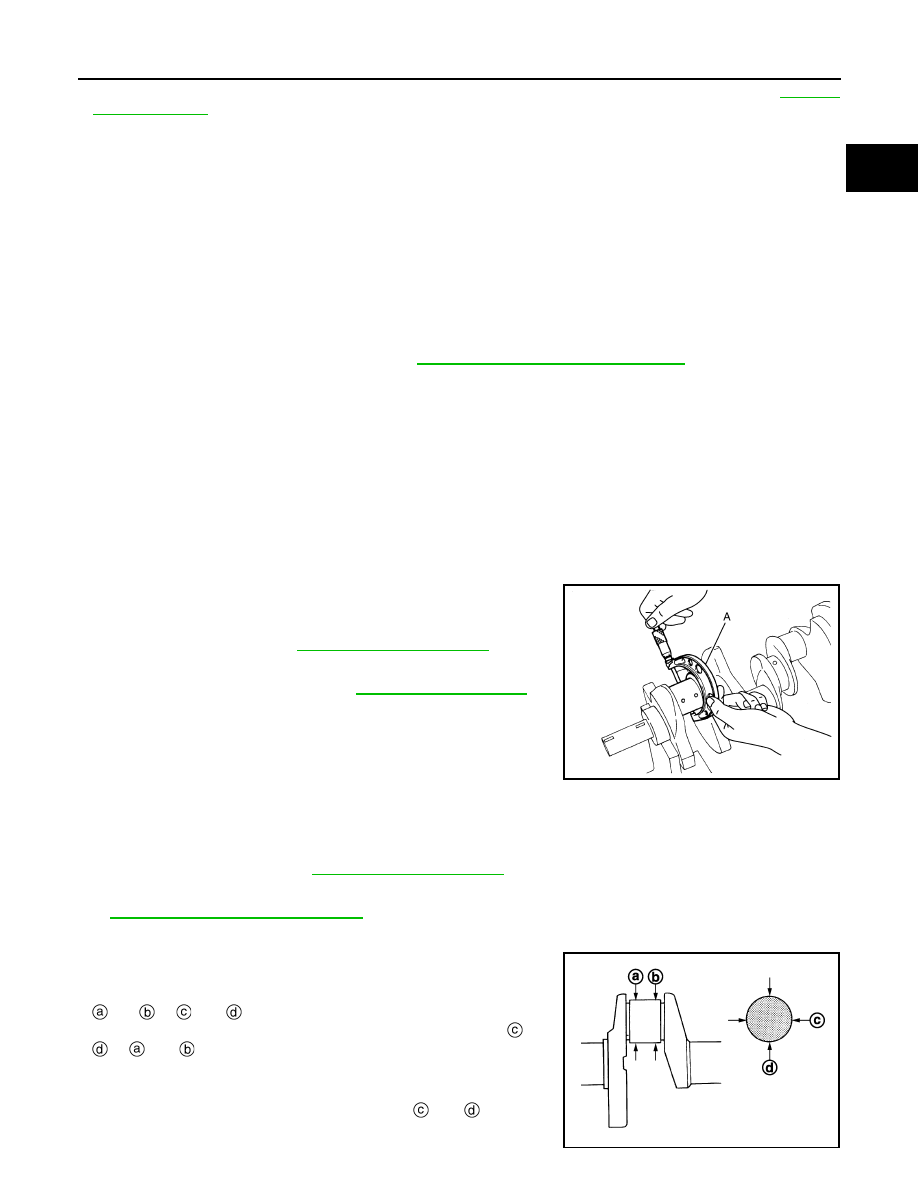
CRANKSHAFT MAIN JOURNAL DIAMETER

• Measure the outer diameter of crankshaft main journals with a

micrometer (A).

• If out of the standard, measure the main bearing oil clearance.

Then use undersize bearing. Refer to 

EM-283, "Main Bearing"

.

CRANKSHAFT PIN JOURNAL DIAMETER 

• Measure the outer diameter of crankshaft pin journal with a micrometer.

• If out of the standard, measure the connecting rod bearing oil clearance. Then use undersize bearing. Refer

to 

EM-284, "Connecting Rod Bearing"

.

OUT-OF-ROUND AND TAPER OF CRANKSHAFT

• Measure the dimensions at four different points as shown in the

figure on each main journal and pin journal with a micrometer. 

• Out-of-round is indicated by the difference in dimensions between

and  

at  

and .

• Taper is indicated by the difference in dimension between 

 and

 at 

 and 

.

Re-bored size calculation: D = A + B - C

where,

A: Piston diameter as measured

B: Piston - to - cylinder bore clearance (standard value)

C: Honing allowance 0.02 mm (0.0008 in)

D: Bored diameter

Standard : 

Refer 

to 

EM-280, "Cylinder Block"

.

JPBIA0228ZZ

Standard

: Refer to 

EM-280, "Cylinder Block"

.

Limit:

Out-of-round [Difference 

between  

and  

]

JPBIA0229ZZ

EM-262

< UNIT DISASSEMBLY AND ASSEMBLY >

[QR25DE]

CYLINDER BLOCK

• If the measured value exceeds the limit, correct or replace crankshaft.
• If corrected, measure the bearing oil clearance of the corrected main journal and/or pin journal. Then select

main bearing and/or connecting rod bearing. Refer to 

EM-284, "Connecting Rod Bearing"

 and/or 

EM-283,

"Main Bearing"

.

CRANKSHAFT RUNOUT 

• Place a V-block (A) on a precise flat table to support the journals

on the both end of the crankshaft.

• Place a dial indicator (B) straight up on the No. 3 journal. 
• While rotating crankshaft, read the movement of the pointer on the

dial indicator. (Total indicator reading)

• If it exceeds the limit, replace crankshaft.

CONNECTING ROD BEARING OIL CLEARANCE

Method by Calculation

• Install connecting rod bearings 

 to connecting rod 

 and cap,

and tighten connecting rod bolts to the specified torque. Refer to

EM-248, "Disassembly and Assembly"

 for tightening procedure. 

• Measure the inner diameter of connecting rod bearing with an inside micrometer.

(Bearing oil clearance) = (Connecting rod bearing inner diameter) – (Crankshaft pin journal diameter)

• If clearance exceeds the limit, select proper connecting rod bearing according to connecting rod big end

diameter and crankshaft pin journal diameter to obtain specified bearing oil clearance. Refer to 

EM-266,

"Connecting Rod Bearing"

.

Method of Using Plastigage

• Remove engine oil and dust on crankshaft pin and the surfaces of each bearing completely. 
• Cut a plastigage slightly shorter than the bearing width, and place it in crankshaft axial direction, avoiding oil

holes.

• Install connecting rod bearings to connecting rod and cap, and tighten connecting rod bolts to the specified

torque. Refer to

EM-248, "Disassembly and Assembly"

 for the tightening procedure. 

CAUTION:

Never rotate crankshaft.

Taper [Difference between 

 and 

 ]

: Refer to 

EM-280, "Cylinder Block"

.

Standard and Limit

: Refer to 

EM-280, 

"Cylinder Block"

.

JSBIA2531ZZ

: Connecting rod bearing cap

: Example

: Inner diameter measuring direction

PBIC3275J

Standard and Limit

: Refer to 

EM-280, "Cylinder Block"

.

CYLINDER BLOCK

EM-263

< UNIT DISASSEMBLY AND ASSEMBLY >

[QR25DE]

C

D

E

F

G

H

I

J

K

L

M

A

EM

N

P

O

• Remove connecting rod cap and bearing, and using the scale (A)

on the plastigage bag, measure the plastigage (B) width. 
NOTE:
The procedure when the measured value exceeds the limit is
same as that described in the “Method by Calculation”.

MAIN BEARING OIL CLEARANCE

Method by Calculation

• Install main bearings 

 to cylinder block 

 and lower cylinder

block 

, and tighten lower cylinder block mounting bolts to the

specified torque. Refer to 

EM-248, "Disassembly and Assembly"

for the tightening procedure. 

• Measure the inner diameter of main bearing with a bore gauge.
(Bearing oil clearance) = (Main bearing inner diameter) – (Crank-
shaft main journal diameter)

• If clearance exceeds the limit, select proper main bearing according to main bearing inner diameter and

crankshaft main journal diameter to obtain specified bearing oil clearance. Refer to 

EM-248, "Disassembly

and Assembly"

.

Method of Using Plastigage

• Remove engine oil and dust on crankshaft main journal and the surfaces of each bearing completely. 
• Cut a plastigage slightly shorter than the bearing width, and place it in crankshaft axial direction, avoiding oil

holes.

• Install main bearings to cylinder block and lower cylinder block, and tighten lower cylinder block mounting

bolts to the specified torque. Refer to 

EM-248, "Disassembly and Assembly"

 for the tightening procedure. 

CAUTION:

Never rotate crankshaft.

• Remove main bearing cap and bearings, and using the scale (A)

on the plastigage bag, measure the plastigage (B) width. 
NOTE:
The procedure when the measured value exceeds the limit is
same as that described in the “Method by Calculation”.

MAIN BEARING CRUSH HEIGHT 

JSBIA2534ZZ

: Example

: Inner diameter measuring direction

PBIC3277J

Standard and Limit

: Refer to 

EM-280, "Cylinder Block"

.

JSBIA2534ZZ

EM-264

< UNIT DISASSEMBLY AND ASSEMBLY >

[QR25DE]

CYLINDER BLOCK

• When main bearing cap is removed after being tightened to the

specified torque with main bearings

installed, the tip end of bear-

ing must protrude

. Refer to 

EM-248, "Disassembly and Assem-

bly"

.

• If the standard is not met, replace main bearings.

CONNECTING ROD BEARING CRUSH HEIGHT

• When connecting rod cap is removed after being tightened to the

specified torque with connecting rod bearings

 installed, the tip

end of bearing must protrude

. Refer to 

EM-248, "Disassembly

and Assembly"

.

• If the standard is not met, replace connecting rod bearings.

LOWER CYLINDER BLOCK MOUNTING BOLT OUTER DIAMETER 

• Perform only with M10 bolts.
• Measure the outer diameters (“d

1

”, “d

2”

) at two positions as shown

in the figure.

• If reduction appears in “A” range, regard it as “d

2

”.

• If it exceeds the limit (a large difference in dimensions), replace

lower cylinder block mounting bolt with a new one.

CONNECTING ROD BOLT OUTER DIAMETER 

• Measure the outer diameter “d” at position as shown in the figure.
• If reduction appears in a position other than “d”, regard it as “d”.

• When “d ” exceeds the limit (when it becomes thinner), replace

connecting rod bolt with a new one.

: Example

Standard

: There must be crush height.

PBIC3279J

: Example

Standard

: There must be crush height.

PBIC3279J

Limit (“d

1

”–“d

2

”): 0.13 mm (0.0051 in) 

PBIC0911E

Limit: 7.75 mm (0.3051 in) 

PBIC0912E


содержание   ..  1089  1090  1091  1092   ..