содержание .. 1040 1041 1042 1043 ..
Nissan X-Trail 32. Manual - part 1042
DRIVE PLATE
EM-65
< UNIT DISASSEMBLY AND ASSEMBLY >
[MR20DD]
C
D
E
F
G
H
I
J
K
L
M
A
EM
N
P
O
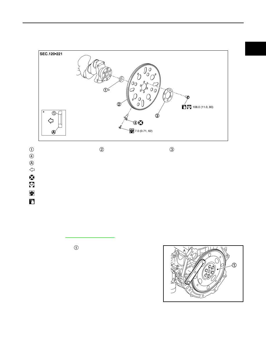
DRIVE PLATE
Exploded View
INFOID:0000000010783713
Removal and Installation
INFOID:0000000010783714
REMOVAL
1.
Remove the engine and the transaxle assembly from the vehicle, and separate the transaxle from the
engine. Refer to
2.
Remove drive plate.
• Secure drive plate
with a stopper plate [SST: KV11105210]
(A), and remove mounting bolts.
• Using TORX socket (size E20), loosen mounting bolts.
• loosen mounting bolts in diagonal order.
CAUTION:
• Never disassemble them.
Pilot converter
Drive plate
Reinforcement plate
Crankshaft position sensor 2
Chamfered
: Crankshaft side
: Always replace after every disassembly.
: N·m (kg-m, ft-lb)
: N·m (kg-m, in-lb)
: Should be lubricated with oil.
JPBIA6837GB
JPBIA4425ZZ