содержание .. 1034 1035 1036 1037 ..
Nissan X-Trail 32. Manual - part 1036
OIL PAN (LOWER)
EM-41
< REMOVAL AND INSTALLATION >
[MR20DD]
C
D
E
F
G
H
I
J
K
L
M
A
EM
N
P
O
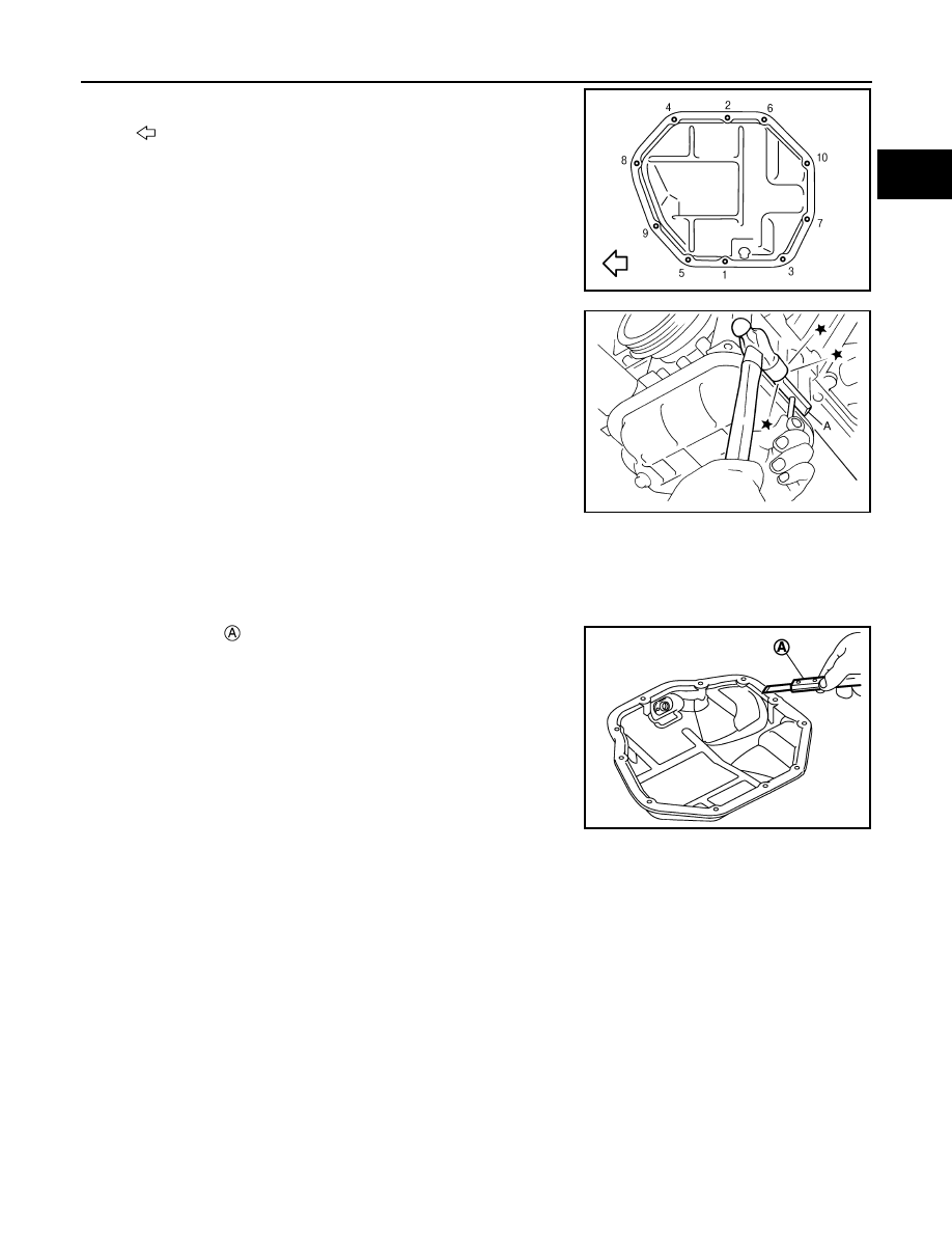
a.
Loosen mounting bolts in reverse order as shown in the figure.
b.
Insert seal cutter [SST: KV10111100] (A) between oil pan (upper)
and oil pan (lower).
CAUTION:
• Be careful not to damage the mating surface.
• Since factory default liquid gasket has better adhesion
than conventional one, never pick the area forcibly with a
screw driver.
INSTALLATION
CAUTION:
Do not reuse O-rings or washers.
Note the following, and install in the reverse order of removal.
1.
Install oil pan (lower) with the following procedure:
a.
Use a scraper
to remove old liquid gasket from mating sur-
faces.
• Also remove old liquid gasket from mating surface of oil pan
(upper).
• Remove old liquid gasket from the bolt holes and threads.
CAUTION:
Never scratch or damage the mating surface when cleaning
off old liquid gasket.
: Engine front
PBIC3146J
JPBIA0276ZZ
PBIC3953E