содержание .. 1018 1019 1020 1021 ..
Nissan X-Trail 32. Manual - part 1020
BRAKE SWITCH
EC-1209
< DTC/CIRCUIT DIAGNOSIS >
[R9M]
C
D
E
F
G
H
I
J
K
L
M
A
EC
N
P
O
2.
Disconnect brake pedal position switch harness connector.
3.
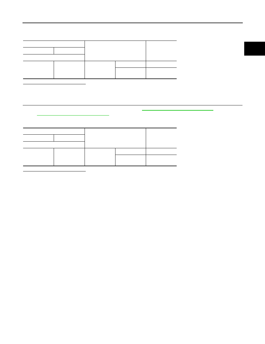
Check the continuity between brake pedal position switch terminals as per the following conditions.
Is the inspection result normal?
YES
>> INSPECTION END
NO
>> GO TO 2.
2.
CHECK BRAKE PEDAL POSITION SWITCH-2
1.
Adjust brake pedal position switch installation. Refer to
BR-11, "Inspection and Adjustment"
(LHD models)
BR-75, "Inspection and Adjustment"
(RHD models).
2.
Check the continuity between brake pedal position switch terminals as per the following conditions.
Is the inspection result normal?
YES
>> INSPECTION END
NO
>> Replace brake pedal position switch.
Brake pedal position switch
Condition
Continuity
+
-
Terminals
1
2
Brake pedal
Fully released
Existed
Slightly de-
pressed
Not existed
Brake pedal position switch
Condition
Continuity
+
-
Terminals
1
2
Brake pedal
Fully released
Existed
Slightly de-
pressed
Not existed