Nissan X-Trail 32. Manual - part 75


  Главная      Nissan     Nissan X-Trail 32 - Service Manual


поиск по сайту            


содержание   ..  73  74  75  76   ..


Nissan X-Trail 32. Manual - part 75


BCS-16

< SYSTEM DESCRIPTION >

SYSTEM

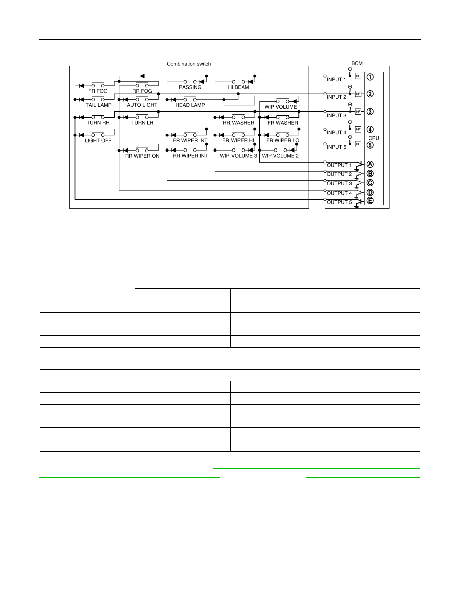
• The circuits between OUTPUT 5 and INPUT 3 and between OUTPUT 1 and INPUT 3 are formed when the

TURN RH switch and FR WASHER switch are turned ON.

• BCM detects the combination switch status signal “3AE” when the signals of OUTPUT 1 and OUTPUT 5 are

input to INPUT 3.

• BCM judges that the TURN RH switch and FR WASHER switch are ON when the signal “3AE” is detected.

WIPER VOLUME DIAL POSITION

• BCM judges the WIP VOLUME 1 - 4 by the status of WIP VOLUME 1, 2 and 3 switches.

4 clicks type

• BCM judges the WIP VOLUME 1 - 5 by the status of WIP VOLUME 1, 2 and 3 switches.

5 clicks type

NOTE:
For details of wiper volume dial position, refer to 

WW-13, "FRONT WIPER AND WASHER SYSTEM (WITH

LIGHT  & RAIN SENSOR) : System Description"

 (with rain sensor) or 

WW-17, "FRONT WIPER AND

WASHER SYSTEM (WITHOUT LIGHT & RAIN SENSOR) : System Description"

 (without rain sensor).

SIGNAL BUFFER SYSTEM

JMMIA1756GB

Wiper volume

Switch status

WIP VOLUME 1

WIP VOLUME 2

WIP VOLUME 3

1

ON

ON

OFF

2

ON

OFF

OFF

3

OFF

OFF

OFF

4

OFF

OFF

ON

Wiper volume

Switch status

WIP VOLUME 1

WIP VOLUME 2

WIP VOLUME 3

1

ON

ON

OFF

2

ON

OFF

OFF

3

OFF

OFF

OFF

4

OFF

OFF

ON

5

OFF

ON

ON

BCS

SYSTEM

BCS-17

< SYSTEM DESCRIPTION >

C

D

E

F

G

H

I

J

K

L

B

A

O

P

N

SIGNAL BUFFER SYSTEM : System Description

INFOID:0000000010688579

SYSTEM DIAGRAM

OUTLINE

BCM has the signal transmission function that outputs/transmits each input/received signal to each unit.

Signal transmission function list

POWER CONSUMPTION CONTROL SYSTEM

JMMIA1814GB

Signal name

Input

Output

Description

Ignition switch ON signal

Push-button ignition switch 
(Push switch) (with Intelligent 
Key system)

• Automatic back door control 

module (CAN)

• IPDM E/R (CAN)

Inputs the push-button ignition 
switch (push switch) signal and 
transmits the ignition switch sta-
tus judged with BCM via CAN 
communication.

Ignition switch (without Intelli-
gent Key system)

Inputs the ignition switch signal 
and transmits the ignition switch 
status judged with BCM via 
CAN communication.

Door switch signal

Any door switch

• Around view monitor control 

unit (CAN)

• Combination meter (CAN)

Inputs the door switch signal 
and transmits it via CAN com-
munication.

BCS-18

< SYSTEM DESCRIPTION >

SYSTEM

POWER CONSUMPTION CONTROL SYSTEM : System Description

INFOID:0000000010688580

SYSTEM DIAGRAM

OUTLINE

• BCM incorporates a power saving control function that reduces the power consumption according to the

vehicle status. 

• BCM switches the status (control mode) by itself with the power saving control function. It performs the sleep

request to each unit (IPDM E/R, combination meter, automatic back door control module and electric parking
brake control module) that operates with the ignition switch OFF.

Normal mode (wake-up)

- CAN communication is normally performed with other units
- Each control with BCM is operating properly

CAN communication sleep mode (CAN sleep)

- CAN transmission is stopped
- Control with BCM only is operating

Low power consumption mode (BCM sleep)

- Low power consumption control is active
- CAN transmission is stopped

LOW POWER CONSUMPTION CONTROL WITH BCM

BCM reduces the power consumption with the following operation in the low power consumption mode.
• The reading interval of the each switches changes from 10 ms interval to 60 ms interval.

Sleep mode activation

• BCM receives the sleep-ready signal (ready) from IPDM E/R, combination meter and AV control unit via

CAN communication.

• BCM transmits the sleep wake up signal (sleep) to each unit when all of the CAN sleep conditions are ful-

filled.

• Each unit stops the transmission of CAN communication with the sleep wake up signal. BCM is in CAN com-

munication sleep mode.

• BCM is in the low power consumption mode and perform the low power consumption control when all of the

BCM sleep conditions are fulfilled with CAN sleep condition.

JMMIA1815GB

BCS

SYSTEM

BCS-19

< SYSTEM DESCRIPTION >

C

D

E

F

G

H

I

J

K

L

B

A

O

P

N

Sleep condition

*1: Without Intelligent Key system
*2: With Intelligent Key system

Wake-up operation

• BCM transmits sleep wake up signal (wake up) to each unit when any condition listed below is established,

and then goes into normal mode from low power consumption mode.

• Each unit starts transmissions with CAN communication by receiving sleep wake up signals.

Wake-up condition

*1: Without Intelligent Key system
*2: With Intelligent Key system

SHIPPING MODE CONTROL SYSTEM

CAN sleep condition

BCM sleep condition

Receiving the sleep-ready signal (ready) from all units

• Ignition switch*

1

: LOCK or OFF

• Push-button ignition switch (push switch)*

2

: No change 2 sec-

onds

• Warning chime: Not operation

• Intelligent Key warning buzzer*

2

: Not operation

• Stop lamp switch: OFF
• Turn signal indicator lamp: Not operation
• Exterior lamp: OFF
• Door lock status: No change
• Meter display signal: Non-transmission
• Door switch status: No change 2 seconds
• Back door opener switch status: No change 2 seconds
• Rear window defogger: OFF
• RAP system: OFF
• CONSULT communication status: Not communication

Wake-up condition

• Receiving the sleep-ready signal (Not-ready) from any units

• Ignition switch*

1

: OFF 

 ON or START

• Key switch*

1

: OFF 

 ON, ON 

 OFF

• Push-button ignition switch (push switch)*

2

: OFF

 ON

• Hazard switch: OFF 

 ON, ON 

 OFF

• HI BEAM switch: OFF 

 ON, ON 

 OFF

• PASSING switch: OFF 

 ON, ON 

 OFF

• HEADLAMP switch: OFF 

 ON, ON 

 OFF

• TAIL LAMP switch: OFF 

 ON

• FR FOG switch: OFF 

 ON, ON 

 OFF

• RR FOG switch: OFF 

 ON, ON 

 OFF

• Driver door switch: OFF 

 ON, ON 

 OFF

• Passenger door switch: OFF 

 ON, ON 

 OFF

• Rear RH door switch: OFF 

 ON, ON 

 OFF

• Rear LH door switch: OFF 

 ON, ON 

 OFF

• Back door switch: OFF 

 ON, ON 

 OFF

• Driver door request switch: OFF 

 ON

• Passenger door request switch: OFF 

 ON

• Back door opener switch: OFF 

 ON

• Back door opener request switch: OFF 

 ON

• Stop lamp switch: OFF 

 ON

• Front door lock assembly (driver side) (unlock sensor): OFF 

 ON, ON 

 OFF

• Remote keyless entry receiver communication: Receiving
• Door lock and unlock switch: NEUTRAL 

 LOCK, NEUTRAL 

 UNLOCK


содержание   ..  73  74  75  76   ..