содержание .. 61 62 63 64 ..
Nissan X-Trail 32. Manual - part 63
AV-244
< DTC/CIRCUIT DIAGNOSIS >
[WITH NAVIGATION]
MICROPHONE SIGNAL CIRCUIT
Is the inspection result normal?
YES
>> Replace NAVI control unit. Refer to
AV-262, "Removal and Installation"
NO
>> Replace microphone. Refer to
AV-272, "Removal and Installation"
.
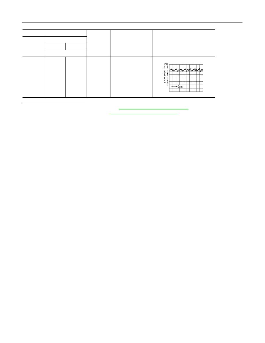
NAVI control unit
Condition
Standard
Reference value
Connector
Terminal
(+)
(–)
Terminal
M28
34
36
Give a
voice.
The value between the
maximum input voltage
and the minimum input
voltage is 4.72V or
less.
PKIB5037J