Nissan X-Trail 32. Manual - part 23


  Главная      Nissan     Nissan X-Trail 32 - Service Manual


поиск по сайту            


содержание   ..  21  22  23  24   ..


Nissan X-Trail 32. Manual - part 23


AV-84

< SYSTEM DESCRIPTION >

[WITH NAVIGATION]

SYSTEM

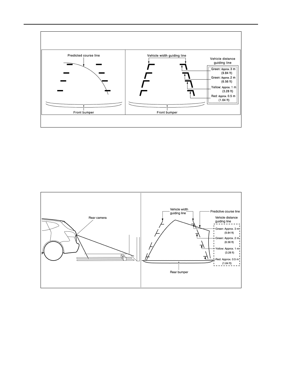
Front view guiding lines

REAR VIEW

• The rear view image is from the rear camera.
• When the selector lever is in the reverse position, the rear view is displayed. Backing and parking are

improved by the images from Birds-Eye view and Front-Side view.

• Display the vehicle width guiding line and vehicle distance guiding line in Rear view and display the predic-

tive course line according to the steering angle.

• The predictive course line is not displayed at the steering neutral position.
• Around view monitor control unit receives the steering angle signal from steering angle sensor via CAN com-

munication, and controls the direction and distance of the predictive course line.

• ON/OFF setting of predictive course line can be performed by CONSULT.

Rear view guiding lines

MOVING OBJECT DETECTION (MOD)

• Moving Object Detection (MOD) is a function that notifies the driver of the presence of moving objects in the

area around the vehicle. MOD detects moving objects from camera image, illuminates frame of view in yel-
low whenever “MOD” icon is displayed in blue, and sounds buzzer in combination meter.

• MOD detects moving objects while camera image is displayed on display.
• Around view monitor control unit performs the following process when moving objects are detected.
- Superimposes yellow frame line on camera image signal and outputs them to display.
- Transmits buzzer output signal to combination meter via CAN communication so that buzzer in combination

meter sounds.

• Around view monitor control unit detects moving objects from camera image according to an image recogni-

tion method called optical flow.

JSNIA0770GB

JSNIA4567GB

AV

SYSTEM

AV-85

< SYSTEM DESCRIPTION >

[WITH NAVIGATION]

C

D

E

F

G

H

I

J

K

L

M

B

A

O

P

• MOD does not detect a background as a moving object when the vehicle moves (when whole screen

moves), but detects a moving object when an actual moving object is displayed on screen. 

• MOD can be set to permanent OFF by the following operation.
- Permanent OFF: Settings can be performed on the information display of the combination meter. 
• Color of “MOD” icon indicates whether or not MOD is operative. “MOD” icon is displayed as shown in the fol-

lowing table. When MOD is operative, “MOD” icon is displayed in blue. When MOD is not operative, “MOD”
icon is displayed in gray or orange. MOD icon is not displayed when MOD is off (permanent off).

• MOD illuminates frame of view in yellow and sounds buzzer, when any of the conditions in the following table

are satisfied.

• MOD does not operate or stops operation when any of the conditions in the following table are satisfied.

“MOD” icon is displayed in gray or orange.

FRONT-SIDE VIEW

• The front-side view image is from the side camera RH. (LHD models)
• The front-side view image is from the side camera LH. (RHD models)
• In Front-Side view, display the vehicle distance guiding line and vehicle width guiding line. 

Operation Condition

View where MOD is operative

Shift position

Vehicle speed

P and N position

0 km/h (0 MPH)

Birds-eye view

R position

0 km/h (0 MPH) or more - less than 8 
km/h (5 MPH)

Rear view

D position

0 km/h (0 MPH) or more - less than 8 
km/h (5 MPH)

Front view

Operation stop condition

“MOD” icon 

color

Note

Front or rear door is open.

Gray

Operation of Birds-eye view stops when door is open.

Back door is open.

Gray

Operation of Birds-eye view and rear view stops when back door is open.

Rear camera installation 
angle is incorrect

Gray

Operation of rear view stops when rear view camera installation angle is 
incorrect.

Front camera image is 
abnormal (Temporary)

Gray

Operation of Birds-eye view and front view stops when front camera im-
age is temporarily abnormal.

Side camera image is ab-
normal (Temporary)

Gray

Operation of Birds-eye view stops when side camera image is temporari-
ly abnormal.

Rear camera image is ab-
normal (Temporary)

Gray

Operation of Birds-eye view and rear view stops when rear camera image 
is temporarily abnormal.

System malfunction

Orange

Refer to 

AV-120, "DTC Index"

AV-86

< SYSTEM DESCRIPTION >

[WITH NAVIGATION]

SYSTEM

Front-side view area and guiding line

NOTE:
RHD model displays a image from side camera LH.

BIRDS-EYE VIEW

• The image from the 4 cameras is cut out and converted into the overhead view, and the surroundings of the

vehicle is displayed in birds-eye view.

• In Birds-Eye view, the invisible area is displayed on the image to specify the boundary of the 4 cameras. 

Birds-Eye view display image

JSNIA0771GB

AWNIA3345GB

AV

SYSTEM

AV-87

< SYSTEM DESCRIPTION >

[WITH NAVIGATION]

C

D

E

F

G

H

I

J

K

L

M

B

A

O

P

Birds-Eye view display area

Camera Image Operation Principle

• If the camera image calibration is incomplete, the applicable camera position is indicated as an error on the

Birds-Eye view display. (Calibration operation is necessary when replacing each camera or when replacing
around view monitor control unit.)

• Around view monitor control unit receives the camera switch signal via CAN communication from NAVI con-

trol unit by pressing the “CAMERA” switch.

• Around view monitor control unit that receives the camera switch signal supplies the power to each camera

and inputs the camera image from each camera. 

• When the selector lever is in the reverse position, around view monitor control unit receives the reverse sig-

nal, supplies the power to each camera, and inputs the camera image from each camera. 

• Around view monitor control unit that receives the camera image signal from each camera cuts out the

required screen for each view, superimposes the camera image, vehicle icon, guiding lines, and outputs
them to the NAVI control unit.

Precautions for Vehicle Width Guide Line and Predictived Course Line Display on The Rear View Monitor Display

Side distance guide lines and predictive course line on the display may be different from actual lines depend-
ing on vehicle conditions and road conditions. 

PRECAUTIONS FOR ROAD CONDITIONS

JSNIA3986GB


содержание   ..  21  22  23  24   ..