содержание .. 698 699 700 701 ..
Nissan Primera P12. Manual - part 700
WT-14
CAN COMMUNICATION
TYPE 25/TYPE26
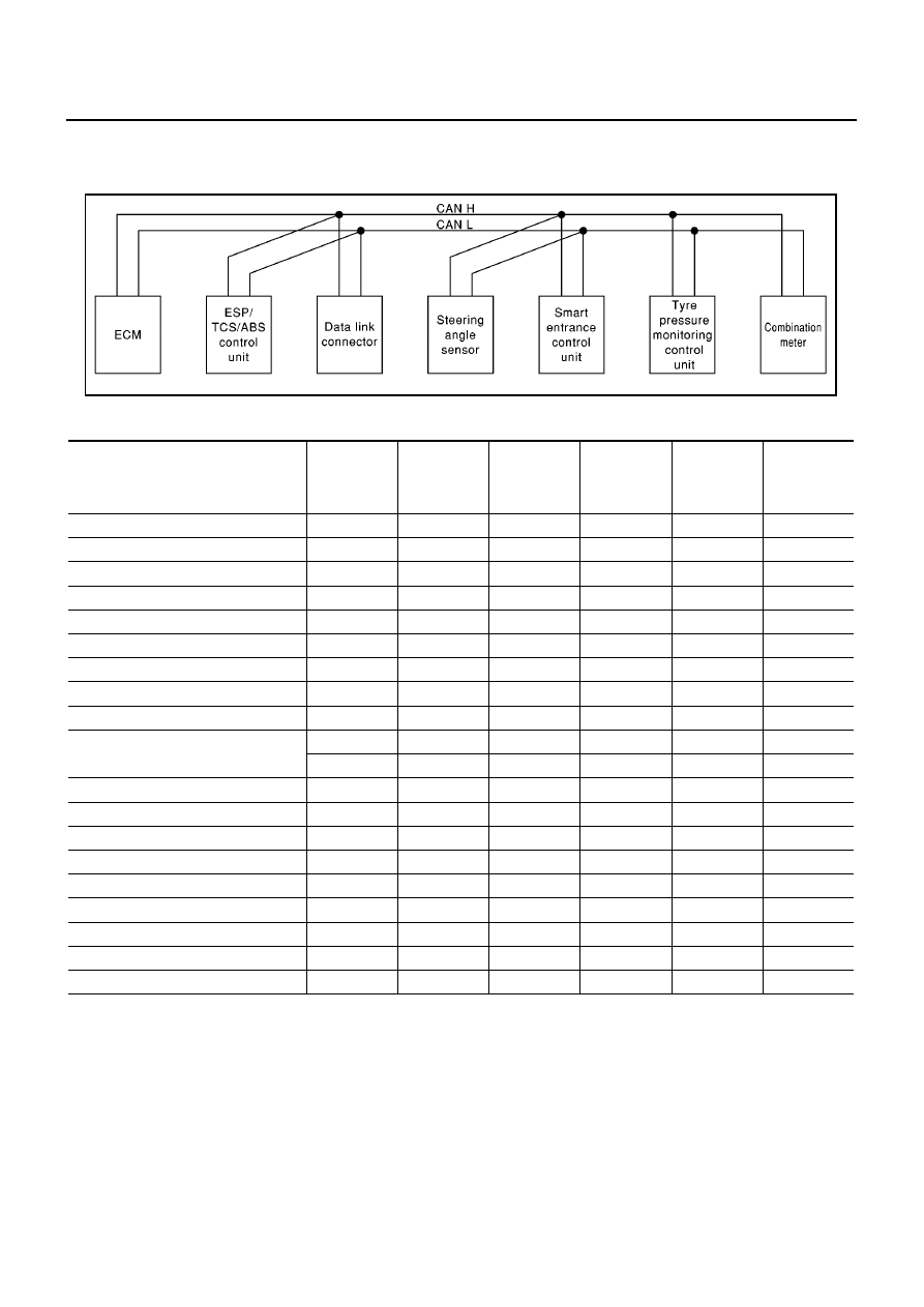
System diagram
LHD models (Type25, Type26)
Input/output signal chart
T: Transmit R: Receive
SKIA1524E
Signals
ECM
ESP/ TCS /
ABS control
unit
Steering
angle sensor
Smart
entrance
control unit
Tyre pres-
sure monitor-
ing control
unit
Combination
meter
Engine speed signal
T
R
R
Accelerator pedal position signal
T
R
ESP operation signal
R
T
TCS operation signal
R
T
ABS operation signal
R
T
Steering angle sensor signal
R
T
MI signal
T
R
Engine coolant temperature signal
T
R
Fuel consumption signal
T
R
Vehicle speed signal
R
T
R
R
T
Seat belt reminder signal
R
T
Lighting switch position signal
T
R
Flashing indicator signal
T
R
Engine cooling fan speed signal
T
R
Child lock indicator signal
T
R
Door switches state signal
T
R
A/C compressor signal
T
R
Glow indicator lamp signal
T
R
Tyre pressure signal
T
R