содержание .. 690 691 692 693 ..
Nissan Primera P12. Manual - part 692
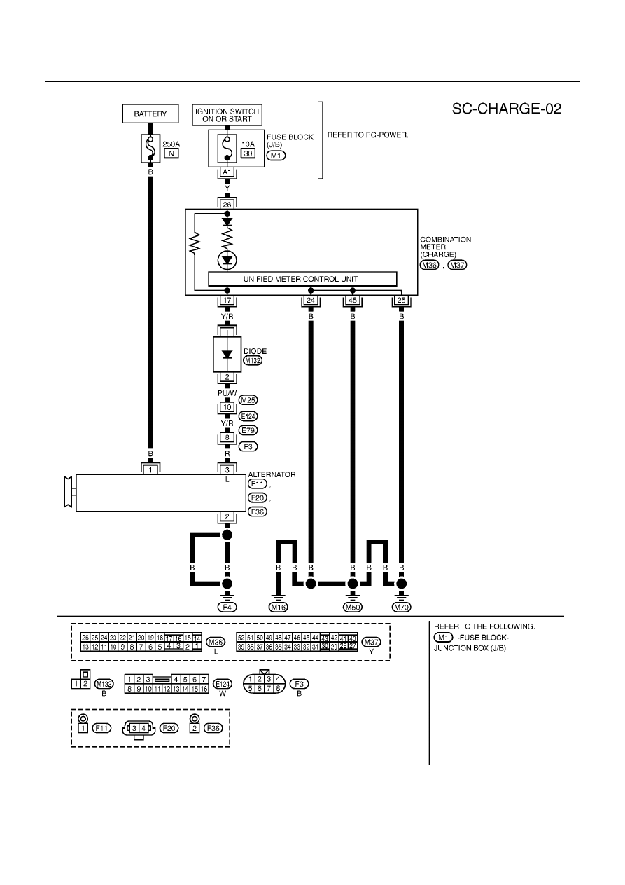
SC-14
CHARGING SYSTEM
Wiring Diagram — CHARGE —/For F9Q Engine
EKS00ATI
MKWA1001E
|
|
|
содержание .. 690 691 692 693 ..
SC-14 CHARGING SYSTEM Wiring Diagram — CHARGE —/For F9Q Engine EKS00ATI MKWA1001E |