содержание .. 570 571 572 573 ..
Nissan Primera P12. Manual - part 572
LAN-200
[CAN]
CAN SYSTEM (TYPE 32)
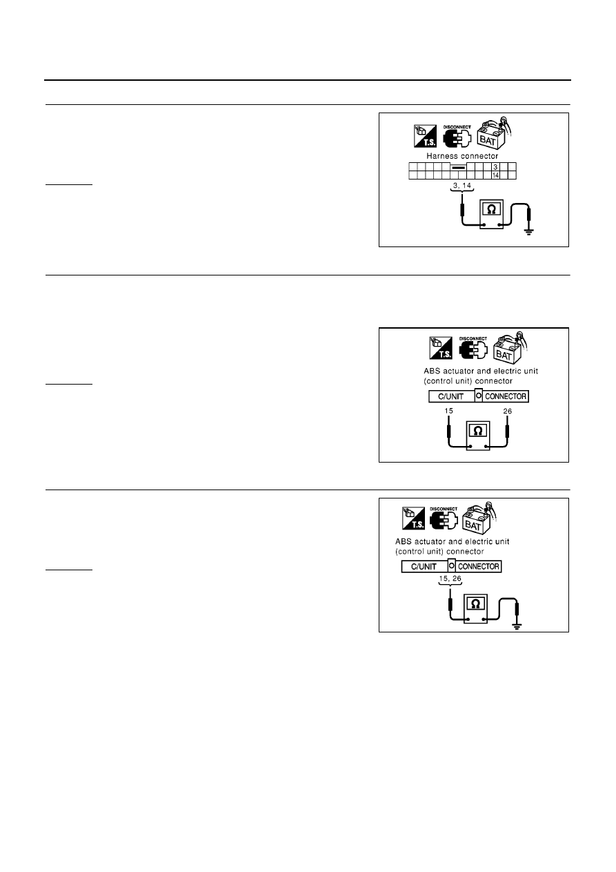
5.
CHECK HARNESS FOR SHORT CIRCUIT
Check continuity between harness connector B101 terminals 3 (L),
14 (R) and ground.
OK or NG
OK
>> GO TO 6.
NG
>> Repair harness between harness connector B101 and
harness connector B107.
6.
CHECK HARNESS FOR SHORT CIRCUIT
1.
Disconnect the following connectors.
–
ABS actuator and electric unit (control unit) connector
–
Harness connector E62
2.
Check continuity between ABS actuator and electric unit (control
unit) harness connector E64 terminals 26 (L) and 15 (R).
OK or NG
OK
>> GO TO 7.
NG
>>
●
Repair harness between ABS actuator and electric
unit (control unit) and harness connector E120.
●
Repair harness between harness connector M120
and harness connector E62.
7.
CHECK HARNESS FOR SHORT CIRCUIT
Check continuity between ABS actuator and electric unit (control
unit) harness connector E64 terminals 26 (L), 15 (R) and ground.
OK or NG
OK
>> GO TO 8.
NG
>>
●
Repair harness between ABS actuator and electric
unit (control unit) and harness connector E120.
●
Repair harness between harness connector M120
and harness connector E62.
3 (L) – ground
: Continuity should not exist.
14 (R) – ground
: Continuity should not exist.
PKIA0880E
26 (L) – 15 (R)
: Continuity should not exist.
PKIA0831E
26 (L) – ground
: Continuity should not exist.
15 (R) – ground
: Continuity should not exist.
PKIA0834E