содержание .. 553 554 555 556 ..
Nissan Primera P12. Manual - part 555
LAN-132
[CAN]
CAN SYSTEM (TYPE 28)
ECM Circuit Check
EKS00B6J
1.
CHECK CONNECTOR
1.
Turn ignition switch OFF.
2.
Disconnect the negative battery cable.
3.
Check following terminals and connector for damage, bend and loose connection. (control module side
and harness side)
●
ECM
●
Harness connector E125
●
Harness connector M130
OK or NG
OK
>> GO TO 2.
NG
>> Repair terminal or connector.
2.
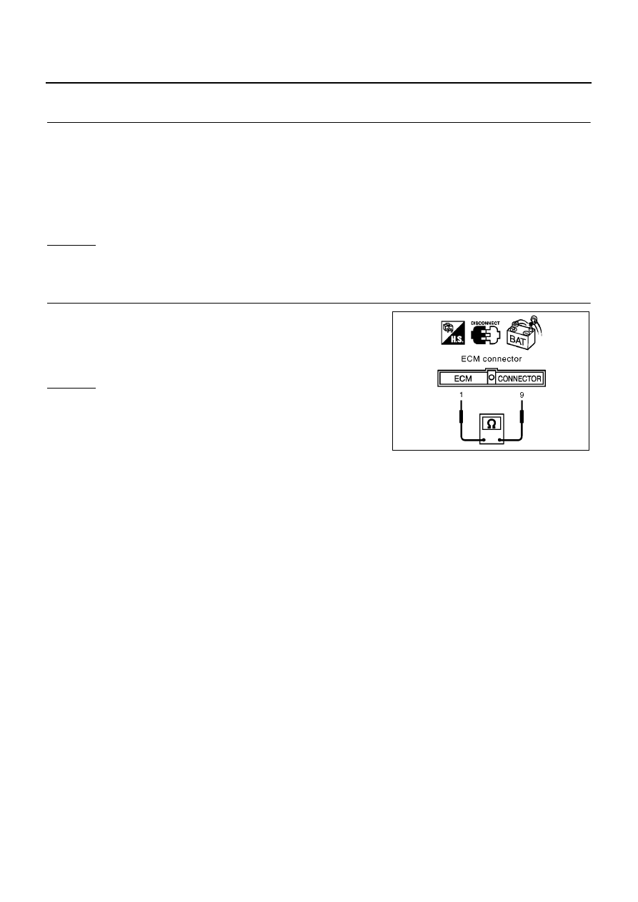
CHECK HARNESS FOR OPEN CIRCUIT
1.
Disconnect ECM connector.
2.
Check resistance between ECM harness connector E81 termi-
nals 1 (L) and 9 (R).
OK or NG
OK
>> Replace ECM.
NG
>> Repair harness between Data link connector and ECM.
1 (L) – 9 (R)
: Approx. 108 – 132
Ω
MKIB0620E