Nissan Primera P12. Manual - part 543


  Главная      Nissan     Nissan Primera P12 - Service Manual


поиск по сайту            


содержание   ..  541  542  543  544   ..


Nissan Primera P12. Manual - part 543


LAN-84

[CAN]

CAN SYSTEM (TYPE 25)

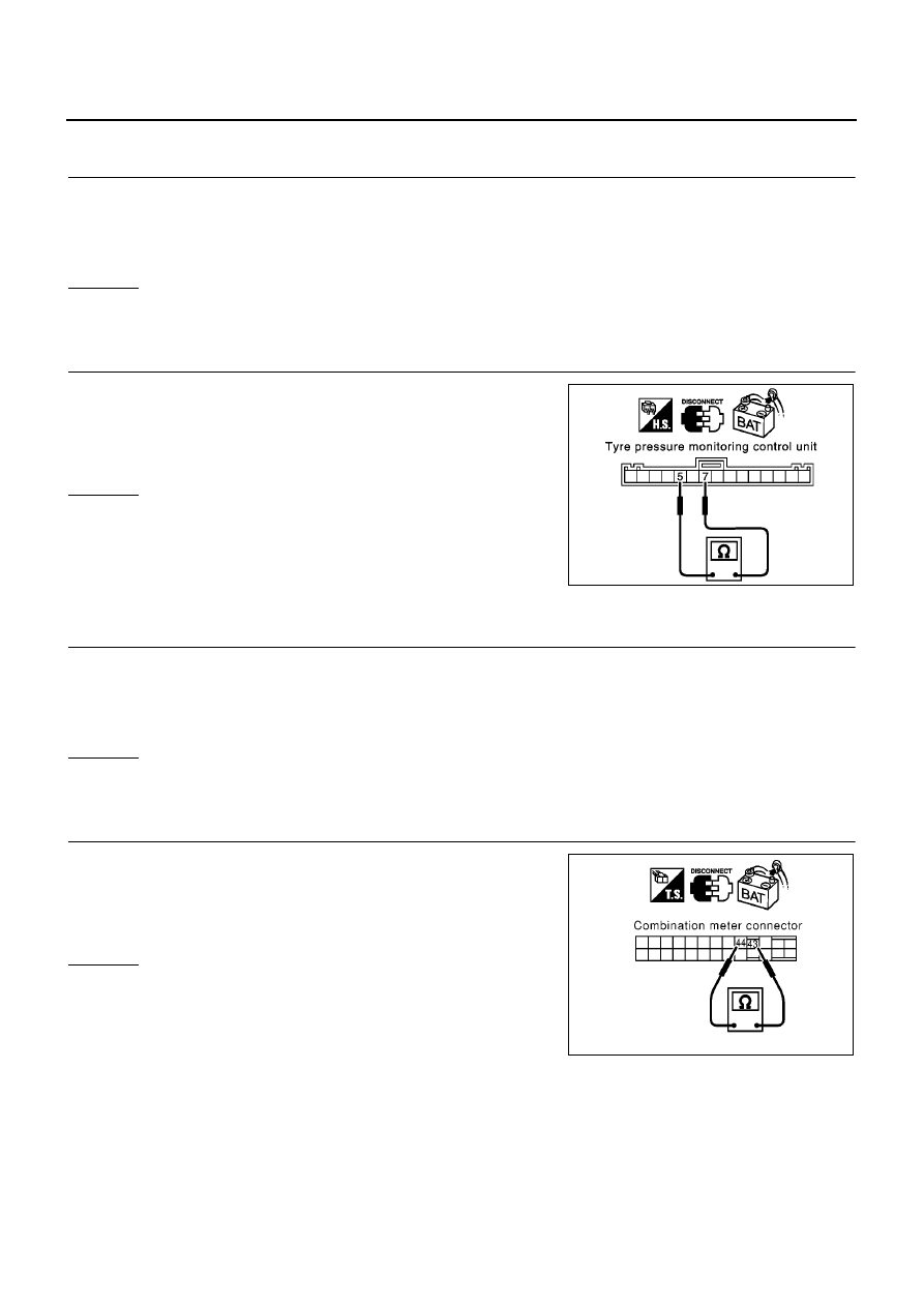
Tyre Pressure Monitoring Control Unit Circuit Check

EKS00ARP

1.

CHECK CONNECTOR

1.

Turn ignition switch OFF.

2.

Disconnect the negative battery cable.

3.

Check terminals and connector of tyre pressure monitoring control unit for damage, bend and loose con-
nection.(control unit side and harness side)

OK or NG

OK

>> GO TO 2.

NG

>> Repair terminal or connector.

2.

CHECK HARNESS FOR OPEN CIRCUIT

1.

Disconnect tyre pressure monitoring control unit connector.

2.

Check resistance between tyre pressure monitoring control unit
harness connector M129 terminals 7(L) and 5(R).

OK or NG

OK

>> Replace tyre pressure monitoring control unit.

NG

>> Repair harness between smart entrance control unit and

tyre pressure monitoring control unit.

Combination Meter Circuit Check

EKS00ARQ

1.

CHECK CONNECTOR

1.

Turn ignition switch OFF.

2.

Disconnect the negative battery cable.

3.

Check terminals and connector of combination meter for damage, bend and loose connection.(meter side
and harness side)

OK or NG

OK

>> GO TO 2.

NG

>> Repair terminal or connector.

2.

CHECK HARNESS FOR OPEN CIRCUIT

1.

Disconnect combination meter connector.

2.

Check resistance between combination meter harness connec-
tor M37 terminals 43(L) and 44(R).

OK or NG

OK

>> Replace combination meter.

NG

>> Repair harness between tyre pressure monitoring con-

trol unit and combination meter.

7(L) – 5(R)

: Approx. 54 – 66

PKIA0863E

43(L) – 44(R)

: Approx. 108 – 132

PKIA0823E

CAN SYSTEM (TYPE 25)

LAN-85

[CAN]

C

D

E

F

G

H

I

J

L

M

A

B

LAN

CAN Communication Circuit Check

EKS00ARR

1.

CHECK CONNECTOR

1.

Turn ignition switch OFF.

2.

Disconnect the negative battery cable.

3.

Check following terminals and connector for damage, bend and loose connection. (meter side, control unit
side, sensor side, control module side and harness side)

Combination meter

Tyre pressure monitoring control unit

Smart entrance control unit

Steering angle sensor

ESP/TCS/ABS control unit

ECM

Between ESP/TCS/ABS control unit and ECM

OK or NG

OK

>> GO TO 2.

NG

>> Repair terminal or connector.

2.

CHECK HARNESS FOR SHORT CIRCUIT

1.

Disconnect the following connectors.

Combination meter connector

Tyre pressure monitoring control unit connector

Smart entrance control unit connector

Steering angle sensor connector

Harness connector M89

Harness connector M130

2.

Check continuity between Data link connector M10 terminals 6
(L) and 14(R).

OK or NG

OK

>> GO TO 3.

NG

>>

Repair harness between smart entrance control unit
and combination meter.

Repair harness between smart entrance control unit
and tyre pressure monitoring control unit.

Repair harness between smart entrance control unit
and steering angle sensor.

Repair harness between smart entrance control unit and data link connector.

Repair harness between harness connector M89 and harness connector M130.

6(L) – 14(R)

: Continuity should not exist.

SKIA6868E

LAN-86

[CAN]

CAN SYSTEM (TYPE 25)

3.

CHECK HARNESS FOR SHORT CIRCUIT

Check continuity between Data link connector M10 terminals 6 (L),
14 (R) and ground.

OK or NG

OK

>> GO TO 4.

NG

>>

Repair harness between smart entrance control unit
and combination meter.

Repair harness between smart entrance control unit
and tyre pressure monitoring control unit.

Repair harness between smart entrance control unit and steering angle sensor.

Repair harness between smart entrance control unit and data link connector.

Repair harness between harness connector M89 and harness connector M130.

4.

CHECK HARNESS FOR SHORT CIRCUIT

1.

Disconnect ESP/TCS/ABS control unit connector.

2.

Check continuity between ESP/TCS/ABS control unit harness
connector B109 terminals 61 (L) and 63(R).

OK or NG

OK

>> GO TO 5.

NG

>> Repair harness between ESP/TCS/ABS control unit and

harness connector B102.

5.

CHECK HARNESS FOR SHORT CIRCUIT

Check continuity between ESP/TCS/ABS control unit harness con-
nector B109 terminals 61 (L), 63 (R) and ground.

OK or NG

OK

>> GO TO 6.

NG

>> Repair harness between ESP/TCS/ABS control unit and

harness connector B102.

6 (L) – ground

: Continuity should not exist.

14 (R) – ground

: Continuity should not exist.

SKIA6874E

61(L) – 63(R)

: Continuity should not exist.

PKIA0818E

61(L) – ground

: Continuity should not exist.

63(R) – ground

: Continuity should not exist.

PKIA0828E

CAN SYSTEM (TYPE 25)

LAN-87

[CAN]

C

D

E

F

G

H

I

J

L

M

A

B

LAN

6.

CHECK HARNESS FOR SHORT CIRCUIT

1.

Disconnect ECM connector.

2.

Check continuity between ECM harness connector E81 termi-
nals 1 (L) and 9 (R).

OK or NG

OK

>> GO TO 7.

NG

>> Repair harness between ECM and harness connector

E125.

7.

CHECK HARNESS FOR SHORT CIRCUIT

Check continuity between ECM harness connector E81 terminals 1
(L), 9 (R) and ground.

OK or NG

OK

>> GO TO 8.

NG

>> Repair harness between ECM and harness connector

E125.

8.

ECM / COMBINATION METER INTERNAL CIRCUIT INSPECTION

Check components inspection. Refer to

LAN-87, "ECM / COMBINATION METER INTERNAL CIRCUIT

INSPECTION"

OK or NG

OK

>> Reconnect all connectors to perform “SELF-DIAG RESULTS” and “DATA MONITOR” for

“ENGINE”, “ABS”, “SMART ENTRANCE”, and “AIR PRESSURE MONITOR” displayed on CON-
SULT-II. Refer to the following:

EC-F9Q-136, “CAN Communication” for “ENGINE”

BRC-94, "Inspection 15 CAN Communication Circuit, ESP/TCS/ABS Control Unit and Steering
Angle Sensor"

for “ABS”

BCS-23, "CAN Communication Line Check"

for “SMART ENTRANCE”

WT-23, "Inspection 4: CAN Communication Line"

for “AIR PRESSURE MONITOR”

NG

>> Replace ECM and/or Combination meter.

Component Inspection

EKS00ARS

ECM / COMBINATION METER INTERNAL CIRCUIT INSPECTION

Remove ECM and Combination meter from vehicle.

Check resistance between ECM terminals 1 and 9.

Check resistance between Combination meter terminals 43 and
44.

1 (L) – 9 (R)

: Continuity should not exist.

MKIB0620E

1 (L) – ground

: Continuity should not exist.

9 (R) – ground

: Continuity should not exist.

MKIB0621E

Unit

Terminal

Resistance value (

)

ECM

1 – 9

Approx. 108 - 132

Combination meter

43 – 44

PKIA0830E


содержание   ..  541  542  543  544   ..