содержание .. 484 485 486 487 ..
Nissan Primera P12. Manual - part 486
FSU-10
TRANSVERSE LINK
TRANSVERSE LINK
PFP:54500
Removal and Installation
EES0013Y
REMOVAL
1.
Remove steering knuckle from transverse link. Refer to
FAX-7, "FRONT WHEEL HUB AND KNUCKLE"
.
2.
Remove mounting nut on lower portion of stabilizer connecting rod.
3.
Remove electrical wires of wheel speed sensor.
4.
Remove suspension crossbar.
5.
Slightly loosen transverse link mounting bolts.
6.
Remove bushing link pin mounting bolts.
7.
Remove transverse link mounting bolts and nuts, and remove transverse link from suspension member.
INSPECTION AFTER REMOVAL
Visual Inspection
Check transverse link and bushing for deformation, cracks, and other damage. Replace the entire transverse
link assembly if cracks, deformation or any other damage is found.
Ball Joint Inspection
CAUTION:
Before measurement, move the ball joint at least ten times by hand to check for smooth movement.
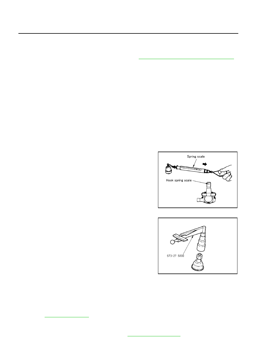
Oscillating Torque Inspection
●
Hook spring scale at cotter pin mounting hole. Confirm spring
scale measurement value is within specifications when ball stud
begins moving.
●
If the value is outside the standard, replace transverse link.
Sliding Torque Inspection
●
Attach mounting nut to ball stud. Check that sliding torque is
within specifications with a preload gauge.
●
If the value is outside the standard, replace transverse link.
Axial End play Inspection
●
Move tip of ball joint in axial direction to check for looseness.
●
If any looseness is noted, replace transverse link.
INSTALLATION
●
Refer to
for tightening torque. Tighten in the reverse order of removal.
●
When installing transverse link, confirm stopper rubber is properly installed (behind front bushing collar).
●
Tighten transverse link mounting bolts with vehicle unladen and all four tires on flat, level ground.
●
After installation, check wheel alignment. Refer to
.
Tensile force:
0.5 - 3.4 N·m (0.05 - 0.35 kg-m, 5 - 30 in-lb)
Measurement on spring balance:
7.94 - 53.97 N (0.81 - 5.50 kg, 1.79 - 12.2 lb)
SEIA0122E
Sliding torque:
0.5 - 3.4 N·m (0.05 - 0.35 kg-m, 5 - 30 in-lb)
FAC1021D
Axial end play
: 0.1 mm (0.004 in) or less