Nissan Primera P12. Manual - part 485


  Главная      Nissan     Nissan Primera P12 - Service Manual


поиск по сайту            


содержание   ..  483  484  485  486   ..


Nissan Primera P12. Manual - part 485


FSU-6

FRONT SUSPENSION ASSEMBLY

On-Vehicle Inspection and Service

EES0013U

LOOSENESS, BACKLASH AND DAMAGE OF MOUNTING PARTS AND CONNECTIONS

Lift vehicle and inspect the following:

Check mounting point of each component for looseness, backlash and damage.

Check lower ball joint end play.

1.

Attach a dial gauge so that the contact rests on the brake caliper.

2.

Set front wheels in a straight-ahead position. Do not depress brake pedal.

3.

Measure axial end play by placing an iron pry bar or something similar between transverse link and steer-
ing knuckle.

CAUTION:

Be careful not to damage ball joint boot.

4.

If axial end play is outside the standard, remove transverse link and check lower ball joint.

Wheel Alignment

EES0013V

DESCRIPTION

Measure wheel alignment under unladen conditions. “Unladen conditions” means that fuel, coolant, and
lubricant are full. However, spare tire, jack, and hand tools should be unloaded.

PRELIMINARY INSPECTION

1.

Check the tires for improper air pressure and wear.

2.

Check road wheels for runout.

3.

Check wheel bearing axial end play.

4.

Check lower ball joint axial end play.

5.

Check strut operation.

6.

Check each mounting point of axle and suspension for looseness and deformation.

7.

Check each link and arm for cracks, deformation, and other damage.

8.

Check the vehicle posture.

INSPECTION OF CAMBER, CASTER, AND KINGPIN INCLINATION ANGLES

Camber, caster, and kingpin inclination angles cannot be adjusted.

Before inspection, mount front wheels onto turning radius gauge. Mount rear wheels onto a stand that has
same height so the vehicle will remain horizontal.
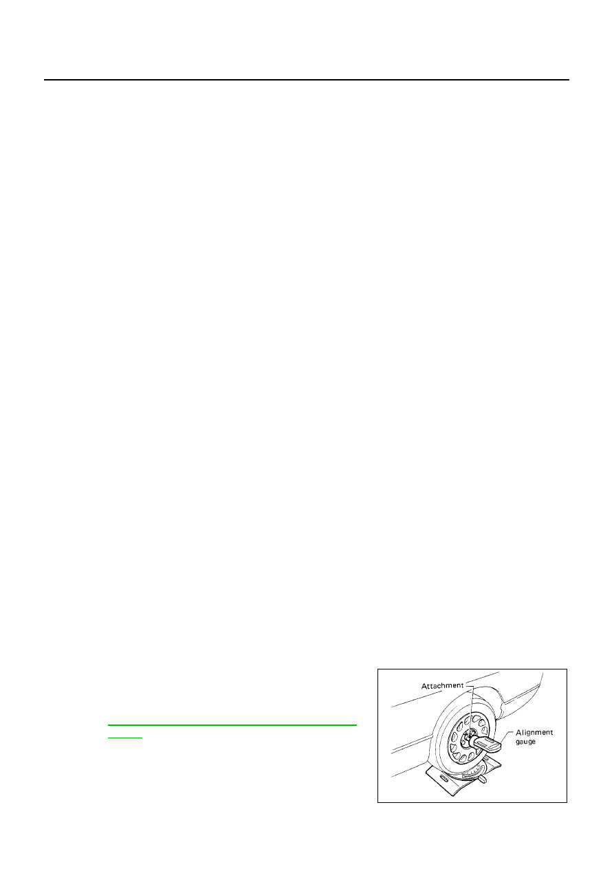
1.

Measure camber, caster and kingpin inclination of both right and
left wheels with a suitable alignment gauge.

2.

If camber, caster or kingpin inclination is not within specification,
inspect front suspension parts. Replace dam-aged or worn out
parts.

1.

Strut spacer

2.

Strut mount insulator

3.

Strut upper bracket

4.

Thrust bearing

5.

Spring upper seat

6.

Upper rubber seat

7.

Bound bumper

8.

Coil spring

9.

Shock absorber (and strut)

10. Cap

11.

Washer

12. Third link

13. Axle assembly

14. Cotter pin

15. Clamp

16. Bushing

17. Stabilizer bar

18. Connecting rod

19. Suspension member

20. Member pin stay

21. Upper link

22. Bushing link pin

23. Transverse link bracket

24. Transverse link

25. Suspension crossbar

Axial end play

: 0 mm (0 in)

Camber, caster and kingpin inclination:

FSU-15, "SERVICE DATA AND SPECIFICATIONS
(SDS)"

SRA096A

FRONT SUSPENSION ASSEMBLY

FSU-7

C

D

F

G

H

I

J

K

L

M

A

B

FSU

Toe-in

Measure toe-in using the following procedure.

WARNING:

Always perform the following procedure on a flat surface.

Make sure that no person is in front of the vehicle before
pushing it.

1.

Bounce front of vehicle up and down to stabilize the posture.

2.

Push the vehicle straight ahead about 5 m (16 ft).

3.

Put a mark on base line of tread (rear side) of both tires at the
same height as hub center. These are measuring points.

4.

Measure distance “A” (rear side).

5.

Push the vehicle slowly ahead to rotate the wheels 180degrees
(1/2 turn).

If the wheels have rotated more than 180 degrees (1/2 turn), try the
above procedure again from the beginning. Never push vehicle
backward.

6.

Measure distance “B” (front side).

STEERING ANGLE INSPECTION

1.

Set wheels in straight-ahead position. Move vehicle to set front wheels on turning radius gauge.

2.

Turn steering wheel fully to right and left, and measure steering angle. Refer to

PS-18, "SERVICE DATA

AND SPECIFICATIONS (SDS)"

.

AFA050

Total toe-in:

FSU-15, "SERVICE DATA AND SPECIFICATIONS
(SDS)"

SFA234AC

FSU-8

COIL SPRING AND SHOCK ABSORBER

COIL SPRING AND SHOCK ABSORBER

PFP:54302

Removal and Installation

EES0013W

REMOVAL

1.

Remove tires. Remove brake caliper and hung it aside.

CAUTION:

Avoid depressing brake pedal with brake caliper removed.

2.

Remove electrical wires of ABS wheel speed sensor from strut.

3.

Remove brake hose lock plate.

4.

Remove mounting bolts securing third link to strut.

5.

Remove mounting nuts on top of strut and remove upper mounting plate and strut from vehicle.

INSTALLATION

Refer to

FSU-5, "Components"

in “Front Suspension Assembly” for tightening torque. Tighten in the

reverse order of removal.

Be sure the identification letters on spring upper seat are posi-
tioned as shown. Also be sure cutout in strut spacer is posi-
tioned as shown. Then install strut.

Disassembly and Assembly

EES0013X

DISASSEMBLY

1.

Install strut attachment to strut and fix it in a vise.

CAUTION:

When installing strut attachment, wrap a shop cloth around
strut to protect it from damage.

2.

Slightly loosen piston rod lock nut.

WARNING:

Do not remove piston rod lock nut completely. If it is
removed completely, coil spring jumps out and may cause
serious damage or injury.

3.

Compress coil spring using a spring compressor.

WARNING:

Make sure that the pawls of the two spring compressors are firmly hooked on the spring. The
spring compressors must be tightened alternately so as not to tilt the spring.

4.

After making sure coil spring is free between upper and lower seats after Step 3. Remove piston rod lock
nut.

5.

Remove small parts on strut.

Remove strut spacer, strut mount insulator, thrust bearings, spring upper seat, and upper rubber seat.
Then remove coil spring.

6.

Remove bound bumper from spring upper seat.

7.

Gradually release spring compressor, and remove coil spring.

INSPECTION AFTER DISASSEMBLY
Strut Inspection

Check strut for deformation, cracks, and damage, and replace if necessary.

Check piston rod for damage, uneven wear, and distortion, and replace if necessary.

Check welded and sealed areas for oil leakage, and replace if necessary.

MEIA0037E

SEIA0124E

COIL SPRING AND SHOCK ABSORBER

FSU-9

C

D

F

G

H

I

J

K

L

M

A

B

FSU

Insulator and Rubber Parts Inspection

Check strut mount insulator for cracks and rubber parts for wear. Replace them if necessary.

Coil Spring Inspection

Check for cracks, wear, and damage, and replace if necessary.

ASSEMBLY

1.

Compress coil spring using a spring compressor, and install it
onto the strut.

CAUTION:

Face the small diameter of coil spring downward. Align
lower end to spring seat as shown in the figure.

WARNING:

Be sure spring compressor is securely attached to coil
spring. Compress coil spring.

2.

Connect bound bumper to spring upper seat.

CAUTION:

Be sure to install bound bumper to spring upper seat
securely.

When installing bound bumper, use soapy water. Do not use machine oil or other lubricants.

3.

Install small parts to the strut.

Connect upper rubber seat, spring upper seat, thrust bearing, strut mount insulator, and strut spacer.
Temporarily install piston rod lock nut.

CAUTION:

Do not reuse piston rod lock nut.

4.

Be sure the identification letters on spring upper seat are posi-
tioned as shown. Also be sure cutout in the strut spacer is posi-
tioned as shown.

5.

Be sure coil spring is properly set in spring rubber seat. Gradu-
ally release spring compressor.

CAUTION:

Be sure upper rubber seat is properly aligned to spring
upper seat and coil spring.

6.

Tighten piston rod lock nut to the specified torque.

7.

Remove strut attachment.

SEIA0125E

MEIA0037E

SEIA0124E


содержание   ..  483  484  485  486   ..