содержание .. 425 426 427 428 ..
Nissan Primera P12. Manual - part 427
EM-54
[YD]
CAMSHAFT
CAMSHAFT
PFP:13001
Removal and Installation
EBS00SNW
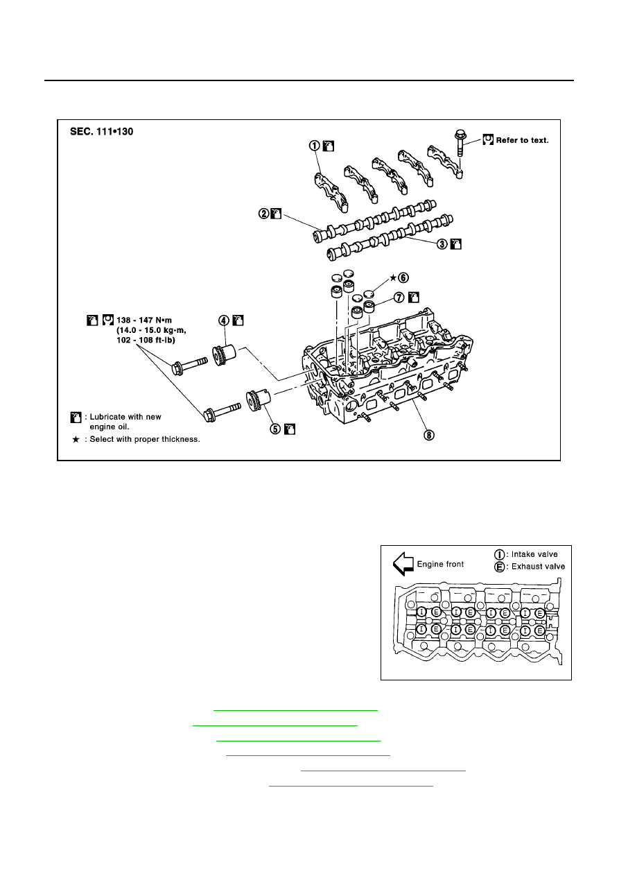
CAUTION:
Apply new engine oil to parts marked in illustration before installation.
●
This engine will have a different valve arrangement from normal
DOHC 4-valve type engines. As both camshafts on this engine
have intake and exhaust camshafts, in this chapter they are
named as follows:
●
Refer to the figure for intake and exhaust valve arrangement.
(The camshafts have, alternately, either an intake valve or an
exhaust valve.)
REMOVAL
1.
Drain engine coolant. Refer to
CO-8, "Changing Engine Coolant"
.
2.
Remove air duct. Refer to
EM-15, "Removal and Installation"
.
3.
Remove rocker cover. Refer to
EM-52, "Removal and Installation"
.
4.
Remove vacuum pump. Refer to
EM-35, "Removal and Installation"
.
5.
Remove injection tube and fuel injector. Refer to
EM-39, "Removal and Installation"
.
6.
Remove secondary timing chain. Refer to
EM-63, "Removal and Installation"
.
SBIA0177E
1.
Camshaft bracket
2.
Camshaft (right side)
3.
Camshaft (left side)
4.
Camshaft sprocket (right side)
5.
Camshaft sprocket (left side)
6.
Adjusting shim
7.
Valve lifter
8.
Cylinder head
Camshaft (Right side)
: Intake manifold side
Camshaft (Left side)
: Exhaust manifold side
SBIA0178E