содержание .. 326 327 328 329 ..
Nissan Primera P12. Manual - part 328
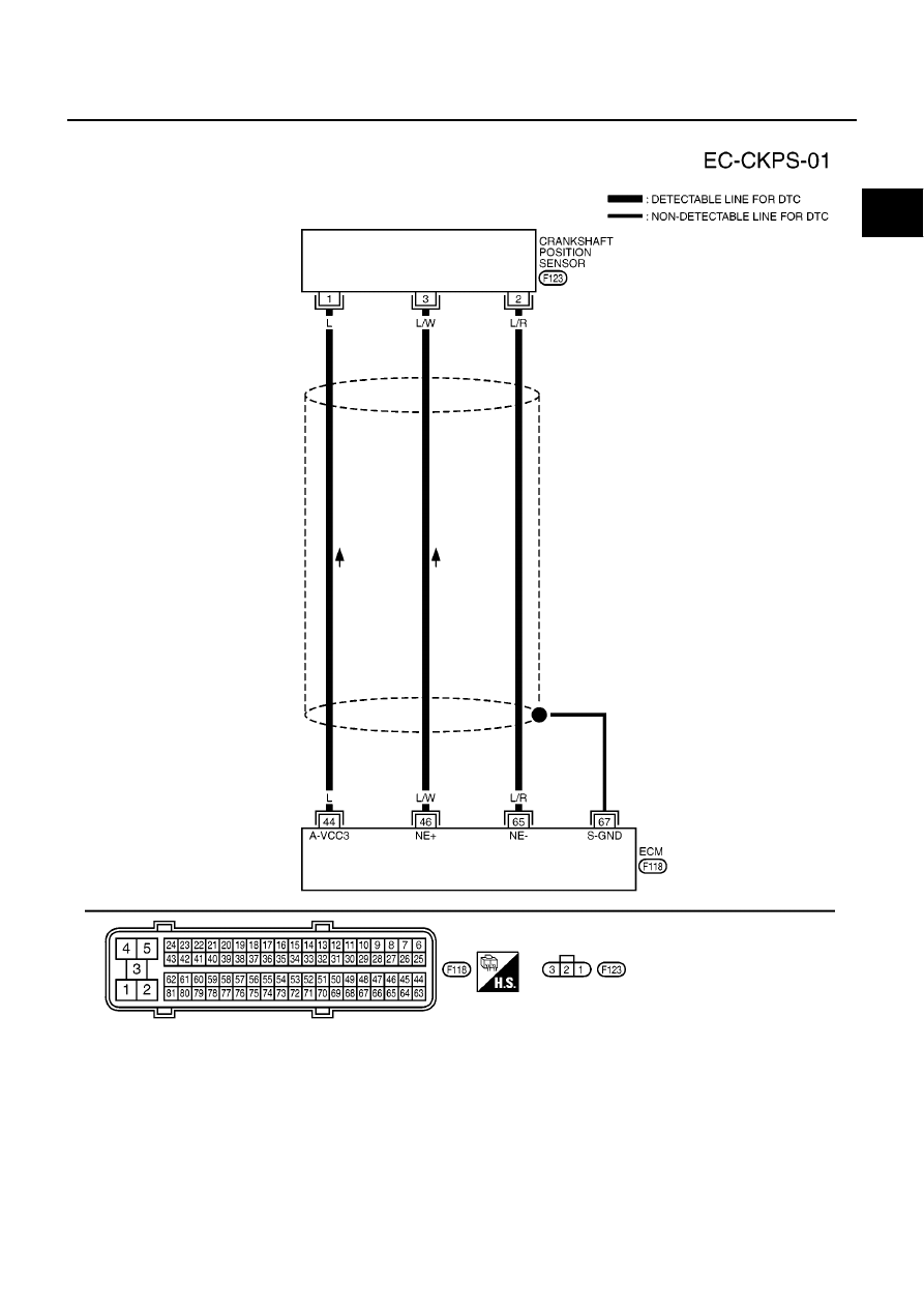
DTC P0335 CKP SENSOR
EC-497
[YD (WITHOUT EURO-OBD)]
C
D
E
F
G
H
I
J
K
L
M
A
EC
Wiring Diagram
EBS01573
MBWA0379E
|
|
|
содержание .. 326 327 328 329 ..
DTC P0335 CKP SENSOR EC-497 [YD (WITHOUT EURO-OBD)] C D E F G H I J K L M A EC Wiring Diagram EBS01573 MBWA0379E |