Nissan Primera P12. Manual - part 258


  Главная      Nissan     Nissan Primera P12 - Service Manual


поиск по сайту            


содержание   ..  256  257  258  259   ..


Nissan Primera P12. Manual - part 258


DTC P0404 EGR VOLUME CONTROL VALVE

EC-217

[YD (WITH EURO-OBD)]

C

D

E

F

G

H

I

J

K

L

M

A

EC

2.

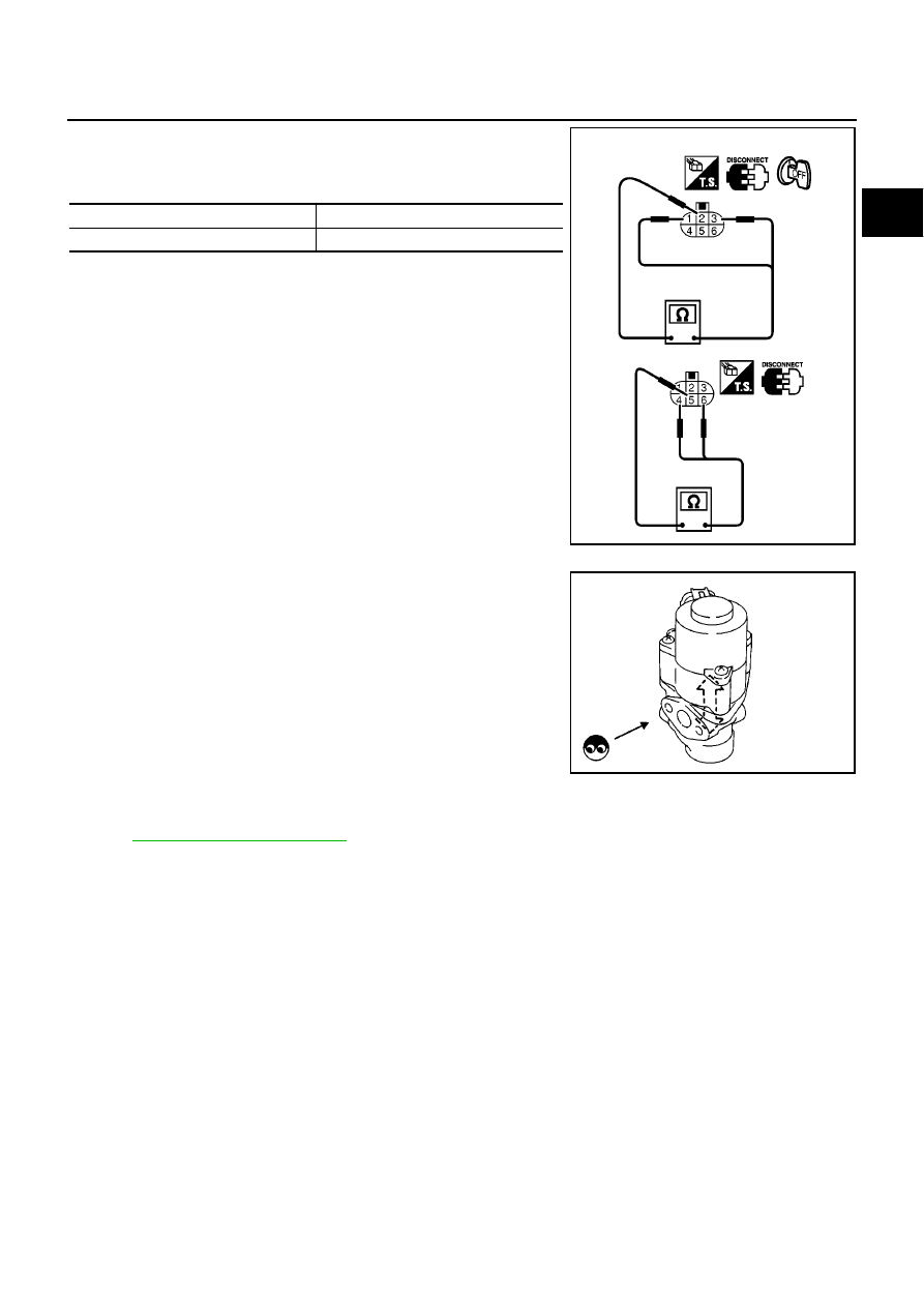
Check resistance between the following terminals.

terminal 2 and terminals 1, 3

terminal 5 and terminals 4, 6

If NG, replace EGR volume control valve.
If OK, go to next step.

3.

Remove EGR volume control valve from cylinder head.

4.

Reconnect EGR volume control valve harness connector.

5.

Turn ignition switch ON and OFF.

6.

Check that EGR volume control valve shaft moves smoothy for-
ward and backward according to the ignition switch position.
If NG, replace EGR volume control valve.
NOTE:
When installing the EGR volume control valve, make sure that
the shaft is in the same position before checking.

Removal and Installation

EBS016L1

EGR VOLUME CONTROL VALVE

Refer to

EM-19, "INTAKE MANIFOLD"

.

Temperature

°

C (

°

F)

Resistance

20 (68)

13 - 17

MBIB0007E

SEF560W

EC-218

[YD (WITH EURO-OBD)]

DTC P0501 ASCD VEHICLE SPEED SENSOR

DTC P0501 ASCD VEHICLE SPEED SENSOR

PFP:24810

Component Description

EBS011VN

The ECM receives vehicle speed sensor signal via CAN communication line. It is sent from combination
meter. The ECM uses this signal for ASCD control. Refer to

EC-348, "AUTOMATIC SPEED CONTROL

DEVICE (ASCD)"

for ASCD functions.

On Board Diagnosis Logic

EBS011VO

This self-diagnosis has the one trip detection logic.
The MI will not light up for this self-diagnosis.

NOTE:

If DTC P0501 is displayed with DTC U1000 first perform the trouble diagnosis for DTC U1000. Refer
to

EC-83, "DTC U1000 CAN COMMUNICATION LINE"

.

DTC Confirmation Procedure

EBS011VP

CAUTION:

Always drive vehicle at a safe speed.

NOTE:
If DTC Confirmation Procedure has been previously conducted, always turn ignition switch OFF and wait at
least 10 seconds before conducting the next test.
TESTING CONDITION:
Step 3 may be conducted with the drive wheels lifted in the shop or by driving the vehicle. If a road test
is expected to be easier, it is unnecessary to lift the vehicle.

WITH CONSULT-II

1.

Start engine (ESP switch OFF).

2.

Select “DATA MONITOR” mode with CONSULT-II.

3.

Drive the vehicle at more than 10 km/h (6 MPH) for at least 5
seconds.

4.

If DTC is detected, go to

EC-219, "Diagnostic Procedure"

.

WITH GST

Follow the procedure “WITH CONSULT-II” above.

DTC No.

Trouble Diagnosis

Name

DTC Detecting Condition

Possible Cause

P0501

Vehicle speed sen-
sor range/perfor-
mance

A change of vehicle speed signal is exces-
sively large during specified time.

Harness or connectors
(The CAN communication line is open or
shorted.)

Combination meter

ABS actuator and electric unit (control unit)
(models without ESP)

ESP/TCS/ABS control unit (models with ESP)

Wheel sensor

ECM

SEF058Y

MBIB1085E

DTC P0501 ASCD VEHICLE SPEED SENSOR

EC-219

[YD (WITH EURO-OBD)]

C

D

E

F

G

H

I

J

K

L

M

A

EC

Diagnostic Procedure

EBS011VQ

1.

CHECK DTC WITH ESP/TCS/ABS CONTROL UNIT (MODELS WITH ESP) OR ABS ACTUATOR AND

ELECTRIC UNIT (CONTROL UNIT) (MODELS WITHOUT ESP)

Refer to

BRC-47, "TROUBLE DIAGNOSIS"

or

BRC-8, "TROUBLE DIAGNOSIS"

.

OK or NG

OK

>> GO TO 2.

NG

>> Repair or replace.

2.

CHECK COMBINATION METER

Check combination meter function.
Refer to

DI-4, "COMBINATION METERS (LHD MODELS)"

or

DI-27, "COMBINATION METERS (RHD MOD-

ELS)"

.

>> INSPECTION END

EC-220

[YD (WITH EURO-OBD)]

DTC P0502 ASCD VEHICLE SPEED SENSOR

DTC P0502 ASCD VEHICLE SPEED SENSOR

PFP:24810

Component Description

EBS011W5

The ECM receives vehicle speed sensor signal via CAN communication line. It is sent from combination
meter. The ECM uses this signal for ASCD control. Refer to

EC-348, "AUTOMATIC SPEED CONTROL

DEVICE (ASCD)"

for ASCD functions.

On Board Diagnosis Logic

EBS011W6

This self-diagnosis has the one trip detection logic.
The MI will not light up for this self-diagnosis.

NOTE:

If DTC P0502 is displayed with DTC U1000 first perform the trouble diagnosis for DTC U1000. Refer
to

EC-83, "DTC U1000 CAN COMMUNICATION LINE"

.

DTC Confirmation Procedure

EBS011W7

CAUTION:

Always drive vehicle at a safe speed.

NOTE:
If DTC Confirmation Procedure has been previously conducted, always turn ignition switch OFF and wait at
least 10 seconds before conducting the next test.
TESTING CONDITION:
Step 3 may be conducted with the drive wheels lifted in the shop or by driving the vehicle. If a road test
is expected to be easier, it is unnecessary to lift the vehicle.

WITH CONSULT-II

1.

Start engine and warm it up to normal operating temperature (ESP switch OFF).

2.

Select “DATA MONITOR” mode with CONSULT-II.

3.

Maintain the following condition for at least 5 seconds.

4.

If DTC is detected, go to

EC-221, "Diagnostic Procedure"

.

WITH GST

Follow the procedure “WITH CONSULT-II” above.

DTC No.

Trouble Diagnosis

Name

DTC Detecting Condition

Possible Cause

P0502

Vehicle speed sen-
sor circuit low input

Vehicle speed signal is excessively low com-
pared with the driving condition.

Harness or connectors
(The CAN communication line is open or
shorted.)

Combination meter

ABS actuator and electric unit (control unit)
(models without ESP)

ESP/TCS/ABS control unit (models with ESP)

Wheel sensor

ECM

CKPS·RPM (TDC)

More than 2,800 rpm

COOLAN TEMP/S

More than 60

°

C (140

°

F)

Clutch pedal

Released

Shift lever

1st position

MBIB1084E


содержание   ..  256  257  258  259   ..