содержание .. 229 230 231 232 ..
Nissan Primera P12. Manual - part 231
DTC P0101 MAF SENSOR
EC-109
[YD (WITH EURO-OBD)]
C
D
E
F
G
H
I
J
K
L
M
A
EC
9.
CHECK MASS AIR FLOW SENSOR
Refer to
EC-109, "Component Inspection"
.
OK or NG
OK
>> GO TO 10.
NG
>> Replace mass air flow sensor.
10.
CHECK INTERMITTENT INCIDENT
Refer to
EC-75, "TROUBLE DIAGNOSIS FOR INTERMITTENT INCIDENT"
.
>> INSPECTION END
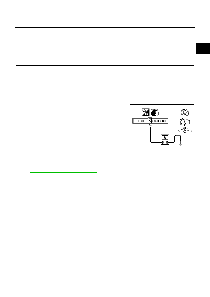
Component Inspection
EBS013L1
MASS AIR FLOW SENSOR
1.
Reconnect harness connectors disconnected.
2.
Start engine and warm it up to normal operating temperature.
3.
Check voltage between ECM terminal 54 (Mass air flow sensor
signal) and ground.
4.
If the voltage is out of specification, disconnect MAF sensor har-
ness connector and connect it again.
Then repeat above check.
Removal and Installation
EBS013L2
MASS AIR FLOW SENSOR
Refer to
EM-15, "AIR CLEANER AND AIR DUCT"
.
Condition
Voltage V
Ignition switch ON (Engine stopped.)
Approx. 0.7
Idle (Engine is warmed up to normal
operating temperature.)
1.8 - 2.3
2,000 rpm (Engine is warmed up to nor-
mal operating temperature.)
2.5 - 3.0
SEF865T