содержание .. 221 222 223 224 ..
Nissan Primera P12. Manual - part 223
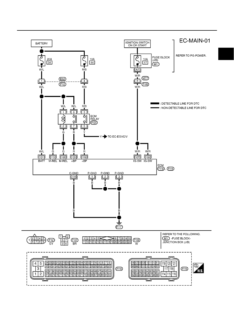
MAIN POWER SUPPLY AND GROUND CIRCUIT
EC-77
[YD (WITH EURO-OBD)]
C
D
E
F
G
H
I
J
K
L
M
A
EC
Wiring Diagram
EBS013JY
MBWA0642E
|
|
|
содержание .. 221 222 223 224 ..
MAIN POWER SUPPLY AND GROUND CIRCUIT EC-77 [YD (WITH EURO-OBD)] C D E F G H I J K L M A EC Wiring Diagram EBS013JY MBWA0642E |