Nissan Primera P12. Manual - part 222


  Главная      Nissan     Nissan Primera P12 - Service Manual


поиск по сайту            


содержание   ..  220  221  222  223   ..


Nissan Primera P12. Manual - part 222


TROUBLE DIAGNOSIS

EC-73

[YD (WITH EURO-OBD)]

C

D

E

F

G

H

I

J

K

L

M

A

EC

NOTE:
Any monitored item that does not match the vehicle being diagnosed is deleted from the display automatically.
*: This signal is converted by ECM internally. Thus, it differs from ECM terminal voltage.

Major Sensor Reference Graph in Data Monitor Mode

EBS013JU

The following are the major sensor reference graphs in “DATA MONITOR” mode.

ACCEL POS SEN, “CKPS·RPM (TDC)”, “MAS AIR/FL SE”

Below is the data for “ACCEL POS SEN”, “CKPS·RPM (TDC)” and “MAS AIR/FL SE” when revving engine
quickly up to 3,000 rpm under no load after warming up engine to the normal operating temperature.
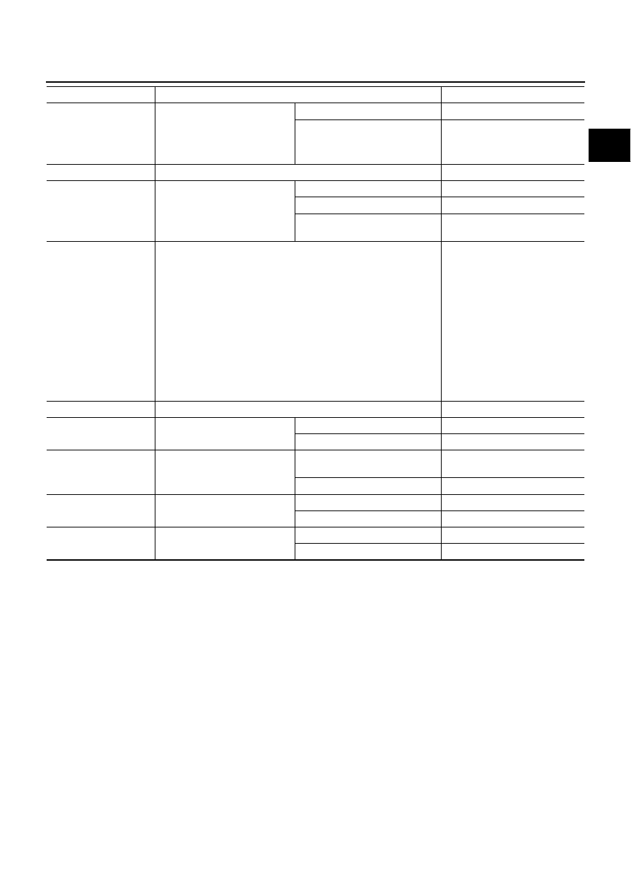
EGR VOL CON/V

Engine: After warming up

Air conditioner switch: OFF

Shift lever: Neutral position

No-load

After 1 minute at idle

More than 10 steps

Revving engine from idle to 3,600
rpm

0 step

INT/A VOLUME

Engine: After warming up, idle the engine

150 - 450 mg/st

INT/M PRES SE [kPa]

Engine: After warming up

Air conditioner switch: OFF

Shift lever: Neutral position

No-load

Idle

Approx. 100 kPa

2,800 rpm

Approx. 126 kPa

4,000 rpm

Approx. 106 kPa

BARO SEN

Ignition switch: ON

Altitude
Approx. 0m: Approx. 100.62 kPa

(1.0062 bar, 1.026 kg/cm

2

, 14.59

psi)
Approx. 1,000 m: Approx. 88.95

kPa (0.8895 bar, 0.907 kg/cm

2

,

12.90 psi)
Approx. 1,500 m: Approx. 83.16

kPa (0.8316 bar, 0.848 kg/cm

2

,

12.06 psi)
Approx. 2,000 m: Approx. 78.36

kPa (0.7836 bar, 0.799 kg/cm

2

,

11.36 psi)

CYL COUNT

Engine is running

1

3

4

2

SET SW

Ignition switch: ON

SET/COAST switch: Released

OFF

SET/COAST switch: Pressed

ON

RESUME/ACC SW

Ignition switch: ON

RESUME/ACCEL switch:
Released

OFF

RESUME/ACCEL switch: Pressed

ON

CANCEL SW

Ignition switch: ON

CANCEL switch: Released

OFF

CANCEL switch: Pressed

ON

MAIN SW

Ignition switch: ON

ON/OFF switch: Released

OFF

ON/OFF switch: Pressed

ON

MONITOR ITEM

CONDITION

SPECIFICATION

EC-74

[YD (WITH EURO-OBD)]

TROUBLE DIAGNOSIS

Each value is for reference, the exact value may vary.

SEF321Y

TROUBLE DIAGNOSIS FOR INTERMITTENT INCIDENT

EC-75

[YD (WITH EURO-OBD)]

C

D

E

F

G

H

I

J

K

L

M

A

EC

TROUBLE DIAGNOSIS FOR INTERMITTENT INCIDENT

PFP:00006

Description

EBS013JV

Intermittent incidents (I/I) may occur. In many cases, the incident resolves itself (the part or circuit function
returns to normal without intervention). It is important to realize that the symptoms described in the customer's
complaint often do not recur on (1st/2nd trip) DTC visits. Realize also that the most frequent cause of I/I occur-
rences is poor electrical connections. Because of this, the conditions under which the incident occurred may
not be clear. Therefore, circuit checks made as part of the standard diagnostic procedure may not indicate the
specific malfunctioning area.

COMMON I/I REPORT SITUATIONS

Diagnostic Procedure

EBS013JW

1.

INSPECTION START

Erase (1st/2nd trip) DTCs. Refer to

EC-34, "HOW TO ERASE EMISSION-RELATED DIAGNOSTIC INFOR-

MATION"

.

>> GO TO 2.

2.

CHECK GROUND TERMINALS

Check ground terminals for corroding or loose connection.
Refer to

GI-24, "How to Perform Efficient Diagnosis for an Electrical Incident"

, “CIRCUIT INSPECTION”,

“Ground Inspection”.

OK or NG

OK

>> GO TO 3.

NG

>> Repair or replace.

3.

SEARCH FOR ELECTRICAL INCIDENT

Perform

GI-24, "How to Perform Efficient Diagnosis for an Electrical Incident"

, “INCIDENT SIMULATION

TESTS”.

OK or NG

OK

>> INSPECTION END

NG

>> Repair or replace.

STEP in Work Flow

Situation

II

The CONSULT-II is used. The SELF-DIAG RESULTS screen shows time data other than “0”.

III

The symptom described by the customer does not recur.

IV

(1st/2nd trip) DTC does not appear during the DTC Confirmation Procedure.

VI

The Diagnostic Procedure for XXXX does not indicate the malfunctioning area.

EC-76

[YD (WITH EURO-OBD)]

MAIN POWER SUPPLY AND GROUND CIRCUIT

MAIN POWER SUPPLY AND GROUND CIRCUIT

PFP:24110

ECM Terminals and Reference Value

EBS013JX

Remarks: Specification data are reference values and are measured between each terminal and ground.

CAUTION:

Do not use ECM ground terminals when measuring input/output voltage. Doing so may result in dam-
age to the ECM's transistor. Use a ground other than ECM terminals, such as the ground.

TERMI-

NAL

NO.

WIRE

COLOR

ITEM

CONDITION

DATA

(DC Voltage and Pulse Signal)

1
2
3

B
B
B

ECM ground

[Engine is running]

Idle speed

Approximately 0V

105

G

ECM relay (self-shutoff)

[Ignition switch ON]
[Ignition switch OFF]

For a few seconds after turning ignition
switch OFF

Approximately 1.2V

[Ignition switch OFF]

More than a few seconds after turning igni-
tion switch OFF

BATTERY VOLTAGE
(11 - 14V)

107
108

W/R
W/R

Ignition switch

[Ignition switch ON]

BATTERY VOLTAGE
(11 - 14V)

113

G

ECM relay (self-shutoff)

[Ignition switch ON]
[Ignition switch OFF]

For a few seconds after turning ignition
switch OFF

Approximately 1.2V

[Ignition switch OFF]

More than a few seconds after turning igni-
tion switch OFF

BATTERY VOLTAGE
(11 - 14V)

114

B

ECM ground

[Engine is running]

Idle speed

Approximately 0V

119

120

R
R

Power supply for ECM

[Ignition switch ON]

BATTERY VOLTAGE
(11 - 14V)

121

W/L

Power supply for ECM
(Back-up)

[Ignition switch OFF]

BATTERY VOLTAGE
(11 - 14V)


содержание   ..  220  221  222  223   ..