Nissan Primera P12. Manual - part 202


  Главная      Nissan     Nissan Primera P12 - Service Manual


поиск по сайту            


содержание   ..  200  201  202  203   ..


Nissan Primera P12. Manual - part 202


REAR VIEW MONITOR

DI-137

C

D

E

F

G

H

I

J

L

M

A

B

DI

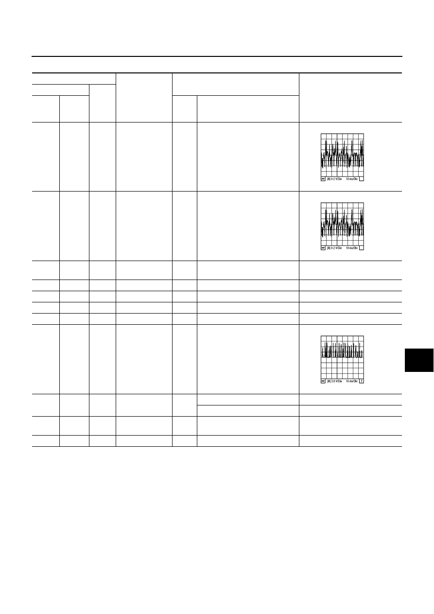
Terminals and Reference Value for Rear View Camera Control Unit

EKS009D7

TERMINALS

ITEM

CONDITION

Voltage [V]

(+)

(–)

TER-

MINAL

WIRE

COLOR

Igni-

tion

switch

Operation

2

R

Ground

Image signal (out-
put

ON

Gear position: “R” position

Approximately 0V

3

W

Ground

Camera image
signal (input)

ON

Gear position “R” position

Approximately 0V

5

PU

Ground

Camera power
output

ON

Gear position: R-position

Approximately 6.5V

6

P

Ground

ACC power

ACC

Battery voltage

7

Y

Ground

Battery power

OFF

Battery voltage

9

Ground

Shield ground

ON

10

Ground

Shield ground

ON

13

L

Ground

Image synchro-
nous signal (out-
put)

ON

Gear position: R-position

Approximately 5V

14

G/W

Ground

Reverse signal
input

ON

Gear position: “R” position

Battery voltage

Gear position: Other position

Approximately 0V

15

PU/W

Ground

Connected recog-
nition signal

ON

Approximately 0V

16

B

Ground

Ground

ON

MKIB0189E

MKIB0189E

MKIB0190E

DI-138

REAR VIEW MONITOR

Power Supply and Ground Circuit Check

EKS009D8

1.

CHECK THE FUSES

Check that the fuses for rear view camera control unit are blown.

OK or NG

OK

>> GO TO 2.

NO

>> If fuse is blown, be sure to eliminate cause of problem before installing new fuse. Refer to

PG-3,

"POWER SUPPLY ROUTING"

.

2.

POWER SUPPLY CIRCUIT CHECK

1.

Disconnect camera controller connector.

2.

Check voltage rear view camera control unit harness connector B130 (LHD models) or B44 (RHD models)
terminal 6 (P) and 7(Y), and ground.

OK or NG

OK

>> GO TO 3.

NO

>> Check harness for open or short between rear view camera control unit and fuse.

3.

GROUND CIRCUIT CHECK

Check the following.

Continuity between rear view camera control unit harness connector B130 (LHD models) or B44 (RHD
models) terminal 16 (B) and ground.

OK or NG

OK

>> Inspection end.

NG

>> Check ground harness.

Unit

Power source

Fuse No.

Rear view camera control unit

Battery Power

33

Ignition switch ACC or ON

1

Terminals

OFF

ACC

ON

(+)

(–)

Connector

Terminal

(Wire color)

B130 or

B44

6 (P)

Ground

0V

Battery
voltage

Battery
voltage

B130 or

B44

7 (Y)

Ground

Battery
voltage

Battery
voltage

Battery
voltage

MKIB0176E

Continuity should exist.

MKIB0717E

REAR VIEW MONITOR

DI-139

C

D

E

F

G

H

I

J

L

M

A

B

DI

Rear View Is Not Displayed With The Selector Lever In R-position

EKS009D9

1.

BACKUP LAMP INSPECTION

1.

Turn ignition switch ON position.

2.

Shift the selector lever to R-position.

Dose backup lamp illuminate?

YES

>> GO TO 2.

NO

>> Check backup lamp system.

2.

CHECK REVERSE POSITION INPUT SIGNAL -I

1.

Turn ignition switch OFF.

2.

Disconnect rear view camera control unit connector.

3.

Turn ignition switch ON.

4.

Shift the selector lever to R-position.

5.

Check voltage between rear view camera control unit harness
connector B130 (LHD models) or B44 (RHD models) terminal 14
(G/W) and ground.

OK or NG

OK

>> GO TO 3 (with navigation system).

OK

>> GO TO 4 (without navigation system).

NG

>> Check harness for open or short between rear view camera control unit and backup lamp switch

(M/T models) or park/neutral position switch (CVT or A/T models).

3.

CHECK REVERSE POSITION INPUT SIGNAL -II

1.

Turn ignition switch OFF.

2.

Disconnect rear AV and NAVI control unit connector.

3.

Turn ignition switch ON.

4.

Shift the selector lever to R-position.

5.

Check voltage between AV and NAVI control unit harness con-
nector M55 terminal 32 (G/W) and ground.

OK or NG

OK

>> GO TO 5.

NG

>> Check harness for open or short between AV and NAVI

control unit and backup lamp switch (M/T models) or park/neutral position switch (CVT or A/T
models).

Battery voltage should exist.

MKIB0178E

Battery voltage should exist.

MKIB0718E

DI-140

REAR VIEW MONITOR

4.

CHECK REVERSE POSITION INPUT SIGNAL -III

1.

Turn ignition switch OFF.

2.

Disconnect display unit connector.

3.

Turn ignition switch ON.

4.

Shift the selector lever to R-position.

5.

Check voltage between display unit harness connector M61 ter-
minal 7 (G/W) and ground.

OK or NG

OK

>> GO TO 5.

NG

>> Check harness for open or short between display unit

and back up lamp switch (M/T models) or park/neutral position switch (CVT or A/T models).

5.

CHECK REAR VIEW CAMERA CIRCUIT

1.

Turn ignition switch OFF.

2.

Disconnect rear view camera control unit connector and rear view camera connector.

3.

Check the following.

Continuity between rear view camera control unit harness connector B130 (LHD models) or B44 (RHD
models) terminal 3 (W) and rear view camera harness connector T5 (sedan models), D91 (wagon mod-
els) or B56 (hatch back models) each terminal 2 (W).

Continuity between rear view camera control unit harness connector B130 (LHD models) or B44 (RHD
models) terminal 5 (PU) and rear view camera harness connector T5(sedan models), D91 (wagon mod-
els) or B56 (hatch back models) each terminal 4 (PU).

Continuity between rear view camera harness connector T5 (sedan models), D91 (wagon models) or B56
(hatch back models) each terminal 3 (B) and ground.

OK or NG

OK

>> GO TO 6.

NG

>> Repair or replace harness.

6.

CHECK REAR VIEW CAMERA CONTROL UNIT OUTPUT SIGNAL

1.

Connect rear view camera control unit connector.

2.

Turn ignition switch ON.

3.

Shift the selector lever to R-position.

4.

Check voltage between rear view camera control unit harness
connector B130 (LHD models) or B44 (RHD models) terminal
5(PU) and ground.

OK or NG

OK

>> GO TO 7.

NG

>> Replace rear view camera control unit.

Battery voltage should exist.

MKIB0719E

Continuity should exist.

Continuity should exist.

Continuity should exist.

MKIB0720E

Approx. 6.5V

MKIB0182E


содержание   ..  200  201  202  203   ..