содержание .. 186 187 188 189 ..
Nissan Primera P12. Manual - part 188
LCD DISPLAY
DI-81
C
D
E
F
G
H
I
J
L
M
A
B
DI
2.
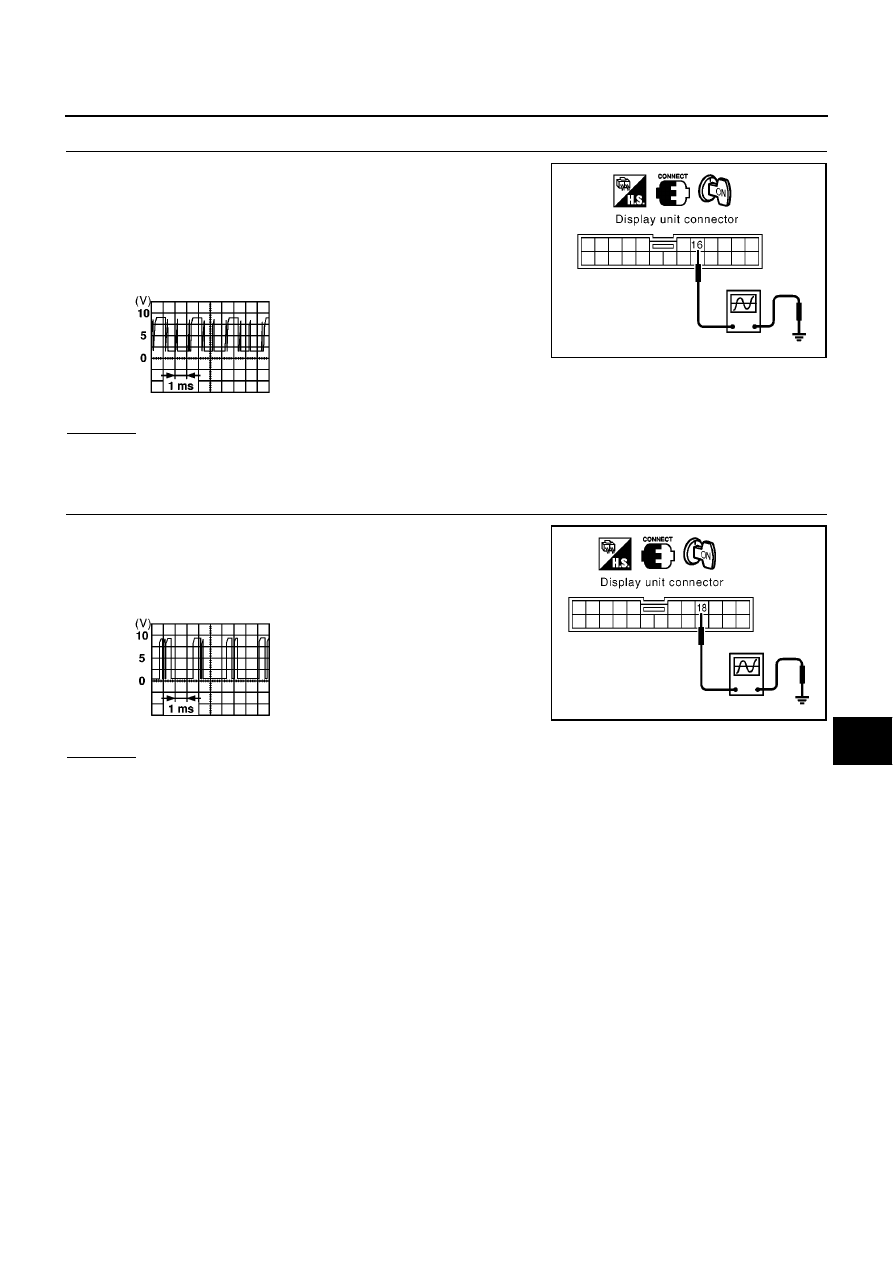
COMMUNICATION SIGNAL (AV–ME) CHECK
1.
Connect display unit connector and combination meter connec-
tor.
2.
Turn ignition switch ON.
3.
Check voltage signal between display unit harness connector
M61 terminal 16 (R) and ground with oscilloscope or CONSULT-
II.
OK or NG
OK
>> GO TO 3.
NG
>> Replace display unit.
3.
COMMUNICATION SIGNAL (ME–AV) CHECK
1.
Turn ignition switch to ON and display.
2.
Check voltage signal between display unit harness connector
M61 terminal 18 (L) and ground with oscilloscope or CONSULT-
II.
OK or NG
OK
>> Replace display unit.
NG
>> Replace combination meter.
MKIB0697E
SKIA0169E
MKIB0698E
SKIA0170E