содержание .. 181 182 183 184 ..
Nissan Primera P12. Manual - part 183
LCD DISPLAY
DI-61
C
D
E
F
G
H
I
J
L
M
A
B
DI
16
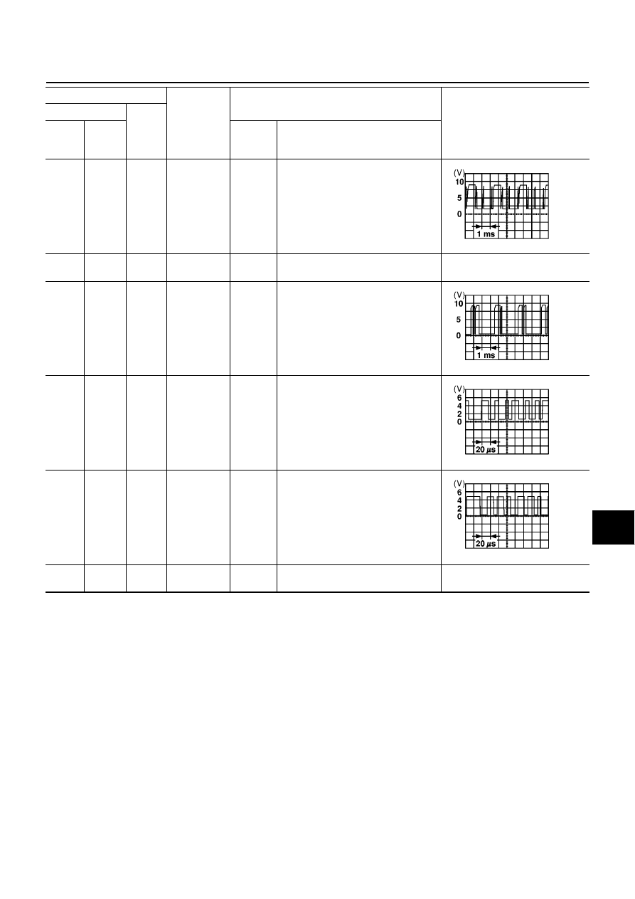
R
Ground
Communica-
tion signal
(AV-ME)
ON
Display the vehicle information screen.
17
—
—
Shield
ground
—
—
—
18
G
Ground
Communica-
tion signal
(ME-AV)
ON
Perform various settings on the vehicle
information screen.
19
L
Ground
Communica-
tion signal (-)
ON
—
20
B/W
Ground
Communica-
tion signal (+)
ON
—
21
–
Ground
Shield
ground
—
—
—
TERMINALS
SIGNAL
CONDITION
VOLTAGE
(+)
(–)
TER-
MINAL
WIRE
COLOR
IGNI-
TION
SWITCH
OPERATION
SKIA0169E
SKIA0170E
SKIA0176E
SKIA0175E