содержание .. 156 157 158 159 ..
Nissan Primera P12. Manual - part 158
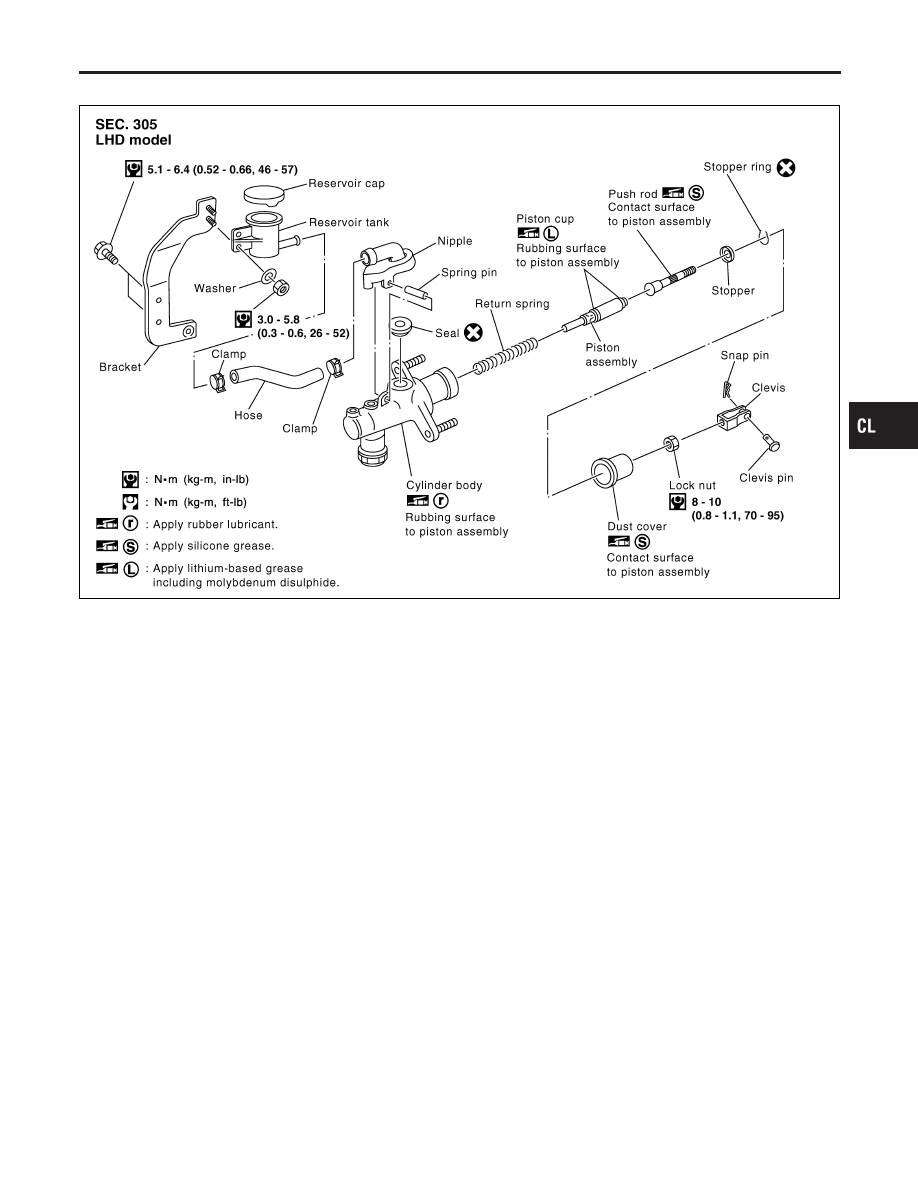
Components
NOCL0007
SCL847-A
Removal
NOCL0008
1.
Drain brake fluid.
CAUTION:
Be careful not to splash brake fluid on painted areas; it may
cause paint damage. If brake fluid is splashed on painted
areas, wash it away with water immediately.
GI
MA
EM
LC
EC
FE
MT
AT
AX
SU
BR
ST
RS
BT
HA
SC
EL
IDX
CLUTCH MASTER CYLINDER
Components
CL-9