Nissan Primera P12. Manual - part 145


  Главная      Nissan     Nissan Primera P12 - Service Manual


поиск по сайту            


содержание   ..  143  144  145  146   ..


Nissan Primera P12. Manual - part 145


TROUBLE DIAGNOSIS

BRC-85

[ESP/TCS/ABS]

C

D

E

G

H

I

J

K

L

M

A

B

BRC

4.

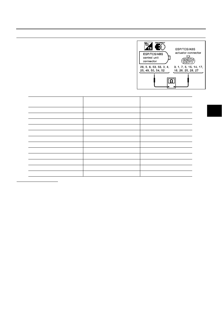
SOLENOID VALVE LINE CHECK

1.

Disconnect connectors for the ESP/TCS/ABS control unit and
the ESP/TCS/ABS actuator.

2.

Check for continuity between the ESP/TCS/ABS control unit
harness connector B109 and the ESP/TCS/ABS actuator har-
ness connector E67, E68.

Is inspection result OK?

OK

>> GO TO 5.

NG

>> Harness disconnection between the ESP/TCS/ABS control unit and the actuator

SFIA0485E

ESP/TCS/ABS control unit

harness connector B109

ESP/TCS/ABS Actuator

harness connector E67, E68

Continuity

26 (W/G)

3 (W/G)

Yes

5 (G/Y)

1 (G/Y)

Yes

6 (L/W)

7 (L/W)

Yes

53 (P)

5 (P)

Yes

55 (R/Y)

15 (R/Y)

Yes

3 (Y/G)

14 (Y/G)

Yes

4 (BR)

17 (BR)

Yes

25 (LG)

16 (LG)

Yes

49 (W/R)

26 (W/R)

Yes

50 (R/G)

25 (R/G)

Yes

54 (W/L)

28 (W/L)

Yes

52 (PU)

27 (PU)

Yes

BRC-86

[ESP/TCS/ABS]

TROUBLE DIAGNOSIS

5.

ACTUATOR SOLENOID INSPECTION

1.

Disconnect the ESP/TCS/ABS actuator connector.

2.

Check the resistance value at the ESP/TCS/ABS actuator.

Is inspection result OK?

OK

>> Perform the ESP/TCS/ABS control unit self-diagnosis again.

NG

>> Replace the ESP/TCS/ABS actuator assembly.

Inspection 8 Actuator Motor, Motor Relay and Circuit

EFS002XE

Inspection procedure

1.

SELF-DIAGNOSIS RESULT CHECK 1

Check the self-diagnosis results.

Are “PUMP MOTOR” and “ACTUATOR RLY” (NOTE) indicated in the self-diagnosis results?

YES

>>

GO TO 2.

NOTE:

“ACTUATOR RLY” on the CONSULT-II self-diagnosis results indicates the malfunction of the

actuator relay and circuit.

SFIA0442E

ESP/TCS/ABS Actuator

connector (actuator side)

ESP/TCS/ABS Actuator

connector (actuator side)

Resistance

3 (W/G)

16

6.0 – 11

1 (G/Y)

16

6.0 – 11

7 (L/W)

16

6.0 – 11

5 (P)

16

6.0 – 11

15 (R/Y)

16

3.0 – 5.0

14 (Y/G)

16

3.0 – 5.0

17 (BR)

16

3.0 – 5.0

16 (LG)

16

3.0 – 5.0

26 (W/R)

16

6.0 – 11.0

25 (R/G)

16

6.0 – 11.0

28 (W/L)

16

3.0 – 5.0

27 (PU)

16

3.0 – 5.0

Self-diagnosis results

CONSULT-II indication item

PUMP MOTOR

ACTUATOR RLY (NOTE)

TROUBLE DIAGNOSIS

BRC-87

[ESP/TCS/ABS]

C

D

E

G

H

I

J

K

L

M

A

B

BRC

2.

SELF-DIAGNOSIS RESULT CHECK 2

1.

Disconnect connectors for the ESP/TCS/ABS control unit and the actuator. Securely connect them again.

2.

Perform the self-diagnosis again.

Are any self-diagnosis items indicated again?

YES

>> GO TO 3.

NO

>> Repair or replace the poorly connected connector.

3.

ACTUATOR MOTOR, MOTOR RELAY POWER SUPPLY CIRCUIT INSPECTION

1.

Disconnect the ESP/TCS/ABS relay box connectors.

2.

Check the voltage between the ESP/TCS/ABS relay box harness connector E65 and body ground.

Is inspection result OK?

OK

>> GO TO 4.

NG

>>

Check the fuse 50A.

Check for continuity between the battery and the ESP/TCS/ABS relay box terminal No. 10.

4.

ACTUATOR MOTOR AND MOTOR RELAY CIRCUIT CHECK

1.

Disconnect connectors for the ESP/TCS/ABS control unit and
the relay box.

2.

Check for continuity between the ESP/TCS/ABS control unit,
the relay, and the actuator harness connectors.

Is inspection result OK?

OK

>> GO TO 5.

NG

>> Harness malfunction between the ESP/TCS/ABS control unit, the relay box and the actuator.

5.

MOTOR RELAY UNIT INSPECTION

Check the motor relay as a unit.

Is inspection result OK?

OK

>> Check the ESP/TCS/ABS control unit power supply circuit.

NG

>> Replace the motor relay.

SFIA0379E

ESP/TCS/ABS relay box

harness connector E65

Body ground

Voltage value

10 (W/L)

Battery voltage (approx. 12V)

ESP/TCS/ABS

control unit

harness connector B109

ESP/TCS/ABS Relay box

harness connector E66

Continuity

20 (R/B)

4 (R/B)

Yes

7 (G/W)

8 (G/W)

Yes

SFIA0443E

BRC-88

[ESP/TCS/ABS]

TROUBLE DIAGNOSIS

Inspection 9 Actuator Relay and Circuit

EFS002XF

Inspection procedure

1.

SELF-DIAGNOSIS RESULT CHECK 1

Check the self-diagnosis results.

Is

MAIN RELAY

indicated in the self-diagnosis results?

>> GO TO 2.

2.

SELF-DIAGNOSIS RESULT CHECK 2

1.

Disconnect the ESP/TCS/ABS control unit connector. Securely connect them again.

2.

Perform the ESP/TCS/ABS control unit self-diagnosis again.

Is the same self-diagnosis item indicated?

YES

>> GO TO 3.

NO

>> Repair or replace the poorly connected connector.

3.

ESP/TCS/ABS CONTROL UNIT GROUND CIRCUIT INSPECTION

Check the ESP/TCS/ABS control unit ground circuit.

Is inspection result OK?

OK

>> GO TO 4.

NG

>> Poorly connection on the ESP/TCS/ABS control unit connector or harness disconnection.

Self-diagnosis results

CONSULT-II indication item

MAIN RELAY

SFIA0381E

ESP/TCS/ABS control unit

harness connector B109

Body ground

Continuity

28 (B)

Yes

29 (B)

Yes


содержание   ..  143  144  145  146   ..