содержание .. 118 119 120 121 ..
Nissan Primera P12. Manual - part 120
BRAKE MASTER CYLINDER
BR-19
C
D
E
G
H
I
J
K
L
M
A
B
BR
7.
Install the reservoir tank to the master cylinder.
CAUTION:
Pay attention to the orientation of the reservoir tank.
8.
Tighten the flange of the cylinder body in the figure.
CAUTION:
●
Using the copper plate or closes to cover the flange for
fixing base.
●
Pay attention to the orientation of the cylinder body.
●
Secure with chamfered pin insert hole on the cylinder
body facing upward.
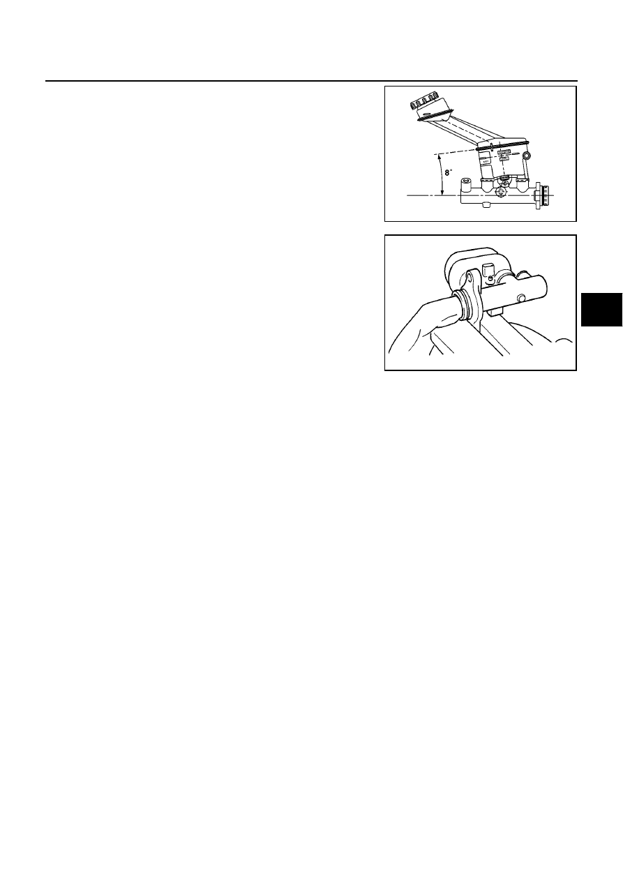
9.
Install reservoir tank to the cylinder body. Tilt reservoir tank as shown in the figure and insert mounting pin.
When mounting pin passes through pinhole in the master cylinder, return reservoir tank to the upright
position. Push mounting pin all the way through the opposite pinhole in the reservoir tank.
CAUTION:
●
Do not reuse reservoir tank mounting pin.
●
Do not reuse reservoir tank.
●
Be sure to insert pin from the chamfered pinhole on the cylinder body.
MFIA0005E
MFIA0003E