содержание .. 90 91 92 93 ..
Nissan Primera P12. Manual - part 92
POWER DOOR LOCK — SUPER LOCK —
BL-77
C
D
E
F
G
H
J
K
L
M
A
B
BL
3.
CHECK SMART ENTRANCE CONTROL UNIT OUTPUT SIGNAL
1.
Connect trunk release actuator and smart entrance control unit connector.
2.
Check voltage between smart entrance control unit connector and ground.
OK or NG
OK
>> Replace back door release actuator.
NG
>> Replace smart entrance control unit.
Child Lock Switch Check
EIS0061O
1.
CHECK CHILD LOCK SWITCH INPUT SIGNAL
Check voltage between smart entrance control unit harness connector and ground.
OK or NG
OK
>> Child lock switch is OK.
NG
>> GO TO 2.
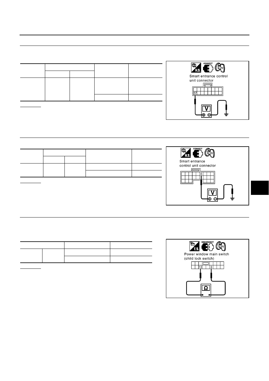
2.
CHECK CHILD LOCK SWITCH
1.
Turn ignition switch OFF.
2.
Disconnect power window main switch connector.
3.
Check continuity between power window main switch terminals 3 and 13.
OK or NG
OK
>> Check the following.
●
Harness for open or short between power window
main switch and smart entrance control unit
●
Power window main switch ground circuit
NG
>> Replace power window main switch.
Connector
Terminal (wire color)
Condition
Voltage (V)
(Approx.)
(+)
(–)
M43
57 (G/B)
Ground
Back door
release switch:
ON
0
Other than above
Battery voltage
MIIB0474E
Connector
Terminals (wire color)
Child lock switch
Voltage (V)
(Approx.)
(+)
(–)
M41
6 (BR)
Ground
Unlock operation
0
Lock operation
5
SIIA1614E
Terminals
Child lock switch
Continuity
3
13
Unlock operation
Yes
Lock operation
No
SIIA1615E