Nissan Primera P12. Manual - part 62


  Главная      Nissan     Nissan Primera P12 - Service Manual


поиск по сайту            


содержание   ..  60  61  62  63   ..


Nissan Primera P12. Manual - part 62


NAVIGATION SYSTEM

AV-91

C

D

E

F

G

H

I

J

L

M

A

B

AV

2.

CHECK SYMPTOM

Turn ignition switch to ACC position. Is screen changed to audio control screen when CD is inserted?

Switches.>>GO TO 3.
Does not switch.>>GO TO 5.

3.

HARNESS CHECK

1.

Turn the ignition switch OFF.

2.

Disconnect multifunction switch connector and Audio unit connector.

3.

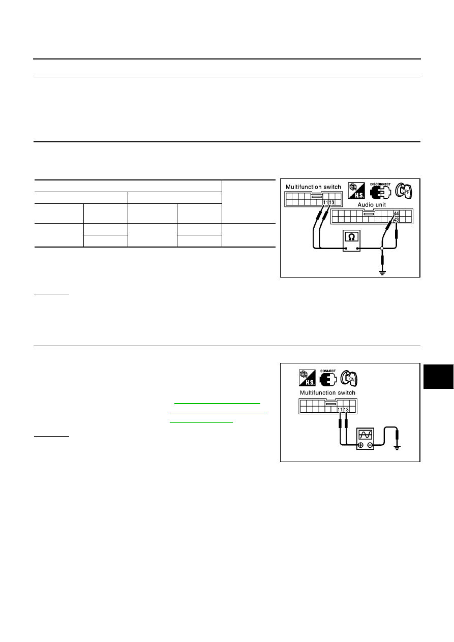
Check continuity between multifunction switch and Audio unit.

4.

Check continuity between multifunction switch harness connec-
tor M49 terminals 11(L), 13 (P) and ground.

OK or NG

OK

>> GO TO 4.

NG

>>

Replace harness.

Check connector housings for disconnected or loose terminals.

4.

COMMUNICATION SIGNAL INSPECTION

1.

Turn ignition switch OFF.

2.

Connect multifunction switch and Audio unit connectors.

3.

Check voltage signal between multifunction switch harness con-
nector M49 terminals 11(L), 13 (P) and ground.

OK or NG

OK

>> Replace audio unit.

NG

>> Replace multifunction switch.

Terminals

Continuity

(+)

(-)

Connector

Terminal

(wire color)

Connector

Terminal

(wire color)

M49

11 (L)

M53

44 (L)

Yes

13 (P)

43 (P)

Continuity should not exist.

SKIA1426E

11 (L), 13 (P) - ground

:

AV-70, "Terminals and

Reference Value for Multi-
function Switch"

MKIB0647E

AV-92

NAVIGATION SYSTEM

5.

HARNESS CHECK

1.

Turn the ignition switch OFF.

2.

Disconnect AV and NAVI control unit connector and Audio unit
connector.

3.

Check continuity between AV and NAVI control unit and Audio
unit.

4.

Check continuity between terminals 47, 48 and 46.

Ok or NG

OK

>> GO TO 6.

NG

>>

Replace harness.

Check connector housings for disconnected or loose
terminals.

6.

COMMUNICATION SIGNAL INSPECTION

1.

Connect audio unit to AV and NAVI control unit connector.

2.

Check voltage signal between AV and NAVI control unit termi-
nals 47 (R), 48 (G) and ground.

OK or NG

OK

>> Replace audio unit.

NG

>> Replace AV and NAVI control unit.

Terminals

Continuity

(+)

(-)

Connector

Terminal

(wire color)

Connector

Terminal

(wire color)

M55

46 (B)

M53

46 (B)

Yes

47 (R)

48 (R)

48 (G)

47 (G)

Terminals

Continuity

(+)

(-)

Connector

Terminal (wire

color)

Connector

Terminal

(wire color)

M55

47 (R), 48 (G)

M55

46(B)

No

MKIB0648E

MKIB0649E

47 (R), 48 (G)-ground

:

AV-65, "Terminals and

Reference Value for AV
and NAVI Control Unit"

MKIB0650E

NAVIGATION SYSTEM

AV-93

C

D

E

F

G

H

I

J

L

M

A

B

AV

Air Conditioning Controls (Only) Are Ineffective (Rear Defogger Control
Excluded)

EKS009K8

1.

HARNESS CHECK

1.

Turn the ignition switch OFF.

2.

Disconnect A/C auto amp. connector and AV and NAVI control unit connector.

3.

Check continuity between A/C auto amp. and AV and NAVI control unit.

4.

Check continuity between AV and NAVI control unit and ground.

Ok or NG

OK

>> GO TO 2.

NG

>>

Check harness between A/C auto amp. and AV and NAVI control unit.

Check connector housings for disconnected or loose terminals.

2.

AC–AV, AV–AC, AC–CLK COMMUNICATION SIGNAL CHECK

1.

Connect A/C AUTO AMP. connector.

2.

Turn the ignition switch ON.

3.

Check voltage between AV and NAVI control unit and ground.

OK or NG

OK

>> GO TO 3.

NG

>> Replace A/C AUTO AMP.

Terminals

Continuity

(+)

(-)

Connector

Terminal

(wire color)

Connector

Terminal

(wire color)

M55

43 (L/R)

M75

10 (L/R)

Yes

44 (L/W)

9 (L/W)

45 (L)

20 (L)

Terminals

Continuity

(+)

(-)

Connector

Terminal (wire color)

M55

43(L/R), 44 (L/W), 45 (L)

Ground

No

MKIB0651E

Terminals

Voltage (V)

(+)

(-)

Connector

Terminal (wire color)

M55

43(L/R), 44(L/W), 45 (L)

Ground

Approx. 3.5 or more

MKIB0652E

AV-94

NAVIGATION SYSTEM

3.

AC - AV, AV– AC, AC - CLK COMMUNICATION SIGNAL CHECK

1.

Connect AV and NAVI control unit connector.

2.

Turn the ignition switch ON.

3.

Check voltage signal between AV and NAVI control unit termi-
nals 43, 44, 45 and ground.

OK or NG

OK

>> Replace A/C auto amplifier.

NG

>> Replace AV and NAVI control unit.

Rear Defogger Does Not Operate

EKS009K9

1.

HARNESS INSPECTION

1.

Turn the ignition switch OFF.

2.

Disconnect multifunction switch connector and smart entrance
control unit connector.

3.

Check continuity between multifunction switch harness connec-
tor M49 terminal 9 (G/B) and smart entrance control unit har-
ness connector M41 terminal 22 (G/B).

4.

Check continuity between multifunction switch harness connec-
tor M49 terminal 9 (G/B) and ground.

OK or NG

OK

>> GO TO 2.

NG

>> Repair harness.

2.

CHECK REAR DEFOGGER ON SIGNAL

1.

Connect multifunction switch connector and smart entrance control unit connector.

2.

Turn the ignition switch ON.

3.

Check continuity between multifunction switch and ground when
rear defogger switch is operated.

OK or NG

OK

>> Replace smart entrance control unit.

NG

>> Replace multifunction switch.

Terminals

Reference signal

(+)

(-)

Connector

Terminal (wire color)

M55

43(L/R), 44(L/W), 45 (L)

Ground

AV-65, "Terminals and Ref-

erence Value for AV and

NAVI Control Unit"

MKIB0653E

Continuity should exist.

Continuity should not exist.

SKIA1434E

Terminals

Rear defogger

switch condition

Continuity

(+)

(-)

Connector

Terminal

(wire color)

M49

9 (G/B)

Ground

Pressed

Yes

Released

No

SKIA1435E


содержание   ..  60  61  62  63   ..