содержание .. 55 56 57 58 ..
Nissan Primera P12. Manual - part 57
NAVIGATION SYSTEM
AV-71
C
D
E
F
G
H
I
J
L
M
A
B
AV
Self-Diagnosis Function
EKS009JT
DESCRIPTION
●
Diagnosis function consists of the self-diagnosis mode performed automatically and the confirmation/
adjustment mode operated manually.
●
Self-diagnosis mode checks connections between all units and performs individual unit diagnosis for all
units in system. Results are displayed on LCD display.
●
Check/adjustment mode is used to perform trouble diagnosis that require operation and judgment by an
operator (trouble that cannot be automatically judged by the system), to check/change the set value, and
to display the error record of the navigation system.
SELF-DIAGNOSIS ITEM
Self-Diagnosis Mode
EKS009JU
OPERATION PROCEDURE
1.
Start the engine.
2.
Turn the audio system off.
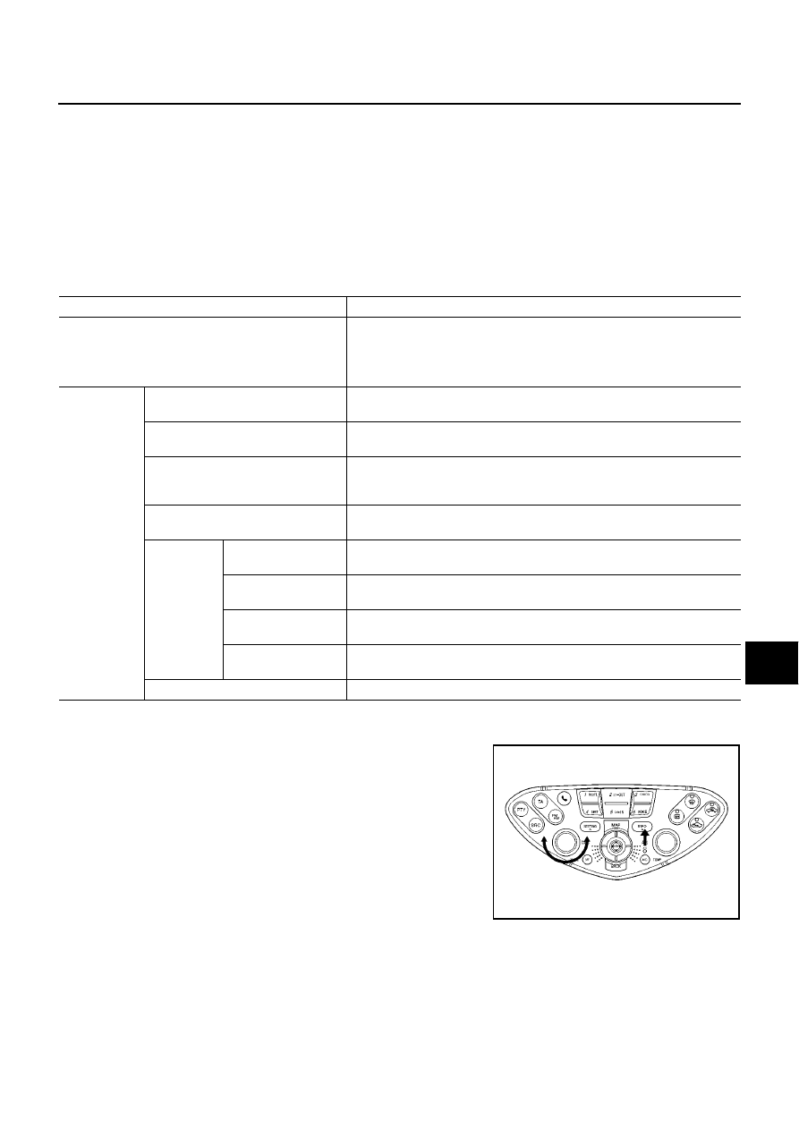
3.
While pressing the “INFO” switch, turn the volume control dial
clockwise or counterclockwise for 30 clicks or more. (When the
self-diagnosis mode is started, a short beep will be heard.)
●
Shifting from current screen to previous screen is performed
by pressing “BACK” switch.
Mode
Diagnosis content
Self-diagnosis
●
Control unit diagnosis (DVD-ROM drive will not be diagnosed when no
map DVD-ROM is in it.)
●
Performs diagnosis of connections between C/U and GPS antenna and
between C/U and all units.
Confirmation/
adjustment
Display
Color tone and shading of the screen can be checked by the display of a
color bar and a gray scale.
Vehicle signals
The following signals can be diagnosed: vehicle speed, parking brake, light,
IGN (IGN SW), and reverse.
History of Errors
Displays the navigation system-related problems that occurred in the past
and the number of their occurrence. When a trouble symptom is selected,
the time and place of the latest occurrence will be shown.
Auto Climate Control
All A/C screen displays on LCD monitor and the A/C SW indicator lamp are
illuminated.
Navigation
Display Longitude &
Latitude
Display the map. Use the joystick to adjust position. Longitude and latitude
will be displayed.
Angle adjustment
Corrects difference between actual turning angle of a vehicle and turning
angle of the car mark on the display.
Distance adjustment
Corrects difference between the current-location mark on the display and
actual position of the vehicle.
Initialize Location
Location memorized by AV and NAVI control unit can be initialized in this
mode.
Service
Service schedule can be changed in this mode.
SKIA1402E