Qashqai J11. Door & Lock - part 56


  Index      Nissan     Qashqai J11. Door & Lock. Service and Repair Manual


Search            copyright infringement  


Content      ..     54      55      56      57     ..


Qashqai J11. Door & Lock - part 56


HAZARD FUNCTION

DLK-897

< DTC/CIRCUIT DIAGNOSIS >

[TYPE 6]

C

D

E

F

G

H

I

J

L

M

A

B

DLK

N

O

P

HAZARD FUNCTION

Component Function Check

INFOID:0000000010672520

1.

CHECK FUNCTION

1.

Select “MULTI REMOTE ENT” of “BCM” using CONSULT.

2.

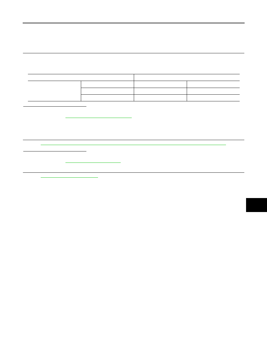
Select “FLASHER” in “ACTIVE TEST” mode.

3.

Check that the function operates normally according to the following conditions.

Is the inspection result normal?

YES

>> Hazard warning lamp circuit is OK.

NO

>> Refer to 

DLK-897, "Diagnosis Procedure"

.

Diagnosis Procedure

INFOID:0000000010672521

1.

CHECK HAZARD OPERATION

Refer to 

EXL-195, "TURN SIGNAL AND HAZARD WARNING LAMP SYSTEM : System Description"

.

Is the inspection result normal?

YES

>> GO TO 2.

NO

>> Refer to 

EXL-303, "Symptom Table"

.

2.

CHECK INTERMITTENT INCIDENT

Refer to 

GI-44, "Intermittent Incident"

.

>> INSPECTION END

Monitor item

Status

FLASHER

LH

Front turn signal lamp LH

Turns ON

RH

Front turn signal lamp RH

Turns ON

OFF

Front turn signal lamp

Turns OFF

DLK-898

< DTC/CIRCUIT DIAGNOSIS >

[TYPE 6]

KEY SWITCH

KEY SWITCH

Component Function Check

INFOID:0000000010672522

1.

CHECK FUNCTION

1.

Select “DOOR LOCK” of “BCM” using CONSULT.

2.

Select “KEY SW” in “DATA MONITOR” mode.

3.

Check that the function operates normally according to the following conditions.

Is the inspection result normal?

YES

>> Key switch is OK.

NO

>> Refer to 

DLK-898, "Diagnosis Procedure"

.

Diagnosis Procedure

INFOID:0000000010672523

1.

CHECK KEY SWITCH POWER SUPPLY CIRCUIT

1.

Turn ignition switch OFF.

2.

Disconnect key switch connector.

3.

Check voltage between key switch harness connector and ground.

Is the inspection result normal?

YES

>> GO TO 3.

NO

>> GO TO 2.

2.

CHECK KEY SWITCH CIRCUIT

1.

Disconnect BCM connector.

2.

Check continuity between key switch harness connector and BCM harness connector.

3.

Check continuity between key switch connector and ground.

Is the inspection result normal?

YES

>> Replace BCM. Refer to 

BCS-135, "Removal and Installation"

.

NO

>> Repair or replace harness.

3.

CHECK GROUND CIRCUIT

Check continuity between key switch connector and ground.

Monitor item

Condition

Status

KEY SW

Keyfob

Inserted in key cylinder

ON

Removed from key cylinder

OFF

Key switch

Ground

Voltage 

Connector

Terminal

M47

1

9 – 16 V

Key switch

BCM

Continuity

Connector

Terminal

Connector

Terminal

M47

1

M69

81

Existed

Key switch

Ground

Continuity 

Connector

Terminal

M47

1

Not existed

Key switch

Ground

Continuity 

Connector

Terminal

M47

2

Existed

KEY SWITCH

DLK-899

< DTC/CIRCUIT DIAGNOSIS >

[TYPE 6]

C

D

E

F

G

H

I

J

L

M

A

B

DLK

N

O

P

Is the inspection result normal?

YES

>> GO TO 4

NO

>> Repair or replace harness.

4.

CHECK INTERMITTENT INCIDENT

Refer to 

GI-44, "Intermittent Incident"

.

Is the inspection result normal?

YES

>> Replace ignition key cylinder.

NO

>> Repair or replace the malfunctioning parts.

DLK-900

< DTC/CIRCUIT DIAGNOSIS >

[TYPE 6]

KEYFOB BATTERY

KEYFOB BATTERY

Component Inspection

INFOID:0000000010672524

1.

CHECK KEYFOB BATTERY

Check by connecting a resistance (approximately 300 

) so that the

current value becomes about 10 mA.

Is the measurement value within the specification?

YES

>> INSPECTION END

NO

>> Replace keyfob battery. Refer to 

DLK-509, "Removal

and Installation"

.

Standard

: Approx. 2.5 - 3.0 V

OCC0607D

POWER SUPPLY AND GROUND CIRCUIT

DLK-901

< DTC/CIRCUIT DIAGNOSIS >

[TYPE 6]

C

D

E

F

G

H

I

J

L

M

A

B

DLK

N

O

P

POWER SUPPLY AND GROUND CIRCUIT

FRONT DOOR

FRONT DOOR : Diagnosis Procedure

INFOID:0000000010672525

1.

CHECK FUSE

Check that the following fuse is not fusing.

Is the fuse fusing?

YES

>> Replace the blown fuse after repairing the affected circuit if a fuse is blown.

NO

>> GO TO 2.

2.

CHECK POWER SUPPLY CIRCUIT

1.

Turn ignition switch OFF.

2.

Disconnect BCM connectors.

3.

Check voltage between BCM harness connector and ground.

Is the measurement value normal?

YES

>> GO TO 3.

NO

>> Repair or replace harness.

3.

CHECK GROUND CIRCUIT

Check continuity between BCM harness connector and ground.

Is the inspection result normal?

YES

>> INSPECTION END

NO

>> Repair or replace harness.

REAR DOOR

REAR DOOR : Diagnosis Procedure

INFOID:0000000010672526

1.

CHECK FUSE

Check that the following fuse is not fusing.

Is the fuse fusing?

YES

>> Replace the blown fuse after repairing the affected circuit if a fuse is blown.

NO

>> GO TO 2.

2.

CHECK POWER SUPPLY CIRCUIT

1.

Turn ignition switch OFF.

2.

Disconnect BCM connectors.

Signal name

Fuse No.

Front door lock actuator power supply

29 (15 A)

(+)

(

)

Voltage

BCM

Connector

Terminal

M68

143

Ground

9 – 16 V

BCM

Ground

Continuity

Connector

Terminal

M68

146

Existed

147

Signal name

Fuse No.

Passenger door and rear door lock actuator power supply

31 (15 A)

DLK-902

< DTC/CIRCUIT DIAGNOSIS >

[TYPE 6]

POWER SUPPLY AND GROUND CIRCUIT

3.

Check voltage between BCM harness connector and ground.

Is the measurement value normal?

YES

>> GO TO 3.

NO

>> Repair or replace harness.

3.

CHECK GROUND CIRCUIT

Check continuity between BCM harness connector and ground.

Is the inspection result normal?

YES

>> INSPECTION END

NO

>> Repair or replace harness.

(+)

(

)

Voltage

BCM

Connector

Terminal

M68

151

Ground

9 – 16 V

BCM

Ground

Continuity

Connector

Terminal

M68

146

Existed

147

UNLOCK SENSOR

DLK-903

< DTC/CIRCUIT DIAGNOSIS >

[TYPE 6]

C

D

E

F

G

H

I

J

L

M

A

B

DLK

N

O

P

UNLOCK SENSOR

Diagnosis Procedure

INFOID:0000000010672527

1.

CHECK BCM OUTPUT SIGNAL

1.

Turn ignition switch OFF.

2.

Disconnect front door lock assembly (driver side) connector.

3.

Check signal between front door lock assembly (driver side) harness connector and ground.

LHD models

RHD models

Is the inspection result normal?

YES

>> GO TO 3.

NO

>> GO TO 2.

2.

CHECK UNLOCK SENSOR CIRCUIT

1.

Disconnect BCM connector.

2.

Check continuity between BCM harness connector and front door lock assembly (driver side) harness
connector.

LHD models

RHD models

3.

Check continuity between BCM harness connector and ground.

Is the inspection result normal?

YES

>> Replace BCM. Refer to 

BCS-135, "Removal and Installation"

.

NO

>> Repair or replace harness.

3.

CHECK UNLOCK SENSOR GROUND CIRCUIT

Check continuity between front door lock assembly (driver side) harness connector and ground.

LHD models

(+)

(–)

Voltage

Front door lock assembly (driver side)

Connector

Terminal

D1

5

Ground

9 – 16 V

(+)

(–)

Voltage

Front door lock assembly (driver side)

Connector

Terminal

D25

4

Ground

9 – 16 V

BCM

Front door lock assembly (driver side)

Continuity 

Connector

Terminal

Connector

Terminal

M69

104

D1

5

Existed

BCM

Front door lock assembly (driver side)

Continuity 

Connector

Terminal

Connector

Terminal

M69

104

D25

4

Existed

BCM

Ground

Continuity 

Connector

Terminal

M69

104

Not existed

Front door lock assembly (driver side)

Ground

Continuity 

Connector

Terminal

D1

4

Existed

DLK-904

< DTC/CIRCUIT DIAGNOSIS >

[TYPE 6]

UNLOCK SENSOR

LHD models

Is the inspection result normal?

YES

>> GO TO 4.

NO

>> Repair or replace harness.

4.

CHECK UNLOCK SENSOR 

Refer to 

DLK-904, "Component Inspection"

Is the inspection result normal?

YES

>> GO TO 5.

NO

>> Replace front door lock assembly (driver side).

5.

CHECK INTERMITTENT INCIDENT 

Refer to 

GI-44, "Intermittent Incident"

.

>> INSPECTION END

Component Inspection

INFOID:0000000010672528

1.

CHECK UNLOCK SENSOR

1.

Turn ignition switch OFF.

2.

Disconnect front door lock assembly (driver side) connector.

3.

Check continuity between front door lock assembly (driver side) terminals.

Is the inspection result normal?

YES

>> INSPECTION END

NO

>> Replace front lock assembly (driver side).

Front door lock assembly (driver side)

Ground

Continuity 

Connector

Terminal

D25

5

Existed

Front door lock assembly (driver side)

Condition

Continuity

Terminal

4

5

Driver side door 

Unlock

Existed

Lock

Not existed

DOOR DOES NOT LOCK/UNLOCK WITH DOOR LOCK AND UNLOCK SWITCH

DLK-905

< SYMPTOM DIAGNOSIS >

[TYPE 6]

C

D

E

F

G

H

I

J

L

M

A

B

DLK

N

O

P

SYMPTOM DIAGNOSIS

DOOR DOES NOT LOCK/UNLOCK WITH DOOR LOCK AND UNLOCK
SWITCH

ALL DOOR

ALL DOOR : Description

INFOID:0000000010672529

All doors do not lock/unlock using door lock and unlock switch.

ALL DOOR : Diagnosis Procedure

INFOID:0000000010672530

1.

CHECK POWER SUPPLY AND GROUND CIRCUIT

Check front door lock and unlock power supply and ground circuit.
Refer to 

DLK-901, "FRONT DOOR : Diagnosis Procedure"

 (front door) or 

DLK-901, "REAR DOOR : Diagnosis

Procedure"

 (rear door).

Is the inspection result normal?

YES

>> GO TO 2.

NO

>> Repair or replace the malfunctioning parts.

2.

CHECK DOOR LOCK AND UNLOCK SWITCH

Check door lock and unlock switch.
Refer to 

DLK-890, "DRIVER SIDE : Component Function Check"

 (driver side) or 

DLK-891, "PASSENGER

SIDE : Component Function Check"

 (passenger side).

Is the inspection result normal?

YES

>> GO TO 3.

NO

>> Repair or replace the malfunctioning parts.

3.

CHECK DOOR LOCK ACTUATOR

Check front door lock assembly (driver side).
Refer to 

DLK-884, "DRIVER SIDE : Component Function Check"

.

Is the inspection result normal?

YES

>> GO TO 4.

NO

>> Repair or replace the malfunctioning parts.

4.

CHECK DOOR SWITCH

Check door switch.
Refer to 

DLK-894, "Component Function Check"

.

Is the inspection result normal?

YES

>> GO TO 5.

NO

>> Repair or replace the malfunctioning parts.

5.

CHECK KEY SWITCH

Check key switch.
Refer to 

DLK-898, "Component Function Check"

.

Is the inspection result normal?

YES

>> GO TO 6.

NO

>> Repair or replace the malfunctioning parts.

6.

REPLACE BCM

1.

Replace BCM. Refer to 

BCS-135, "Removal and Installation"

.

2.

Confirm the operation after replacement.

Is the result normal?

YES

>> INSPECTION END

NO

>> Check intermittent incident. Refer to 

GI-44, "Intermittent Incident"

.

FRONT DOOR

DLK-906

< SYMPTOM DIAGNOSIS >

[TYPE 6]

DOOR DOES NOT LOCK/UNLOCK WITH DOOR LOCK AND UNLOCK SWITCH

FRONT DOOR : Description

INFOID:0000000010672531

Front doors do not lock/unlock using door lock and unlock switch.

FRONT DOOR : Diagnosis Procedure

INFOID:0000000010672532

1.

CHECK POWER SUPPLY AND GROUND CIRCUIT

Check front door lock and unlock power supply and ground circuit.
Refer to 

DLK-901, "FRONT DOOR : Diagnosis Procedure"

Is the inspection result normal?

YES

>> GO TO 2.

NO

>> Repair or replace the malfunctioning parts.

2.

CHECK DOOR LOCK ACTUATOR

Check front door lock actuator (driver side).
Refer to 

DLK-884, "DRIVER SIDE : Component Function Check"

.

Is the inspection result normal?

YES

>> GO TO 3.

NO

>> Repair or replace the malfunctioning parts.

3.

REPLACE BCM

1.

Replace BCM. Refer to 

BCS-135, "Removal and Installation"

.

2.

Confirm the operation after replacement.

Is the result normal?

YES

>> INSPECTION END

NO

>> Check intermittent incident. Refer to 

GI-44, "Intermittent Incident"

.

REAR DOOR

REAR DOOR : Description

INFOID:0000000010672533

Rear doors do not lock/unlock using door lock and unlock switch.

REAR DOOR : Diagnosis Procedure

INFOID:0000000010672534

1.

CHECK POWER SUPPLY AND GROUND CIRCUIT

Check rear doors lock and unlock power supply and ground circuit.
Refer to 

DLK-901, "REAR DOOR : Diagnosis Procedure"

Is the inspection result normal?

YES

>> GO TO 2.

NO

>> Repair or replace the malfunctioning parts.

2.

CHECK DOOR LOCK ACTUATOR

Check rear door lock actuator.
Refer to 

DLK-887, "REAR LH : Component Function Check"

 (LH) and 

DLK-888, "REAR RH :

Component Function Check"

 (RH).

Is the inspection result normal?

YES

>> GO TO 3.

NO

>> Repair or replace the malfunctioning parts.

3.

REPLACE BCM

1.

Replace BCM. Refer to 

BCS-135, "Removal and Installation"

.

2.

Confirm the operation after replacement.

Is the result normal?

YES

>> INSPECTION END

NO

>> Check intermittent incident. Refer to 

GI-44, "Intermittent Incident"

.

DRIVER SIDE

DOOR DOES NOT LOCK/UNLOCK WITH DOOR LOCK AND UNLOCK SWITCH

DLK-907

< SYMPTOM DIAGNOSIS >

[TYPE 6]

C

D

E

F

G

H

I

J

L

M

A

B

DLK

N

O

P

DRIVER SIDE : Description

INFOID:0000000010672535

Driver side door does not lock/unlock using door lock and unlock switch.

DRIVER SIDE : Diagnosis Procedure

INFOID:0000000010672536

1.

CHECK DOOR LOCK ACTUATOR

Check front door lock assembly (driver side).
Refer to 

DLK-884, "DRIVER SIDE : Component Function Check"

.

Is the inspection result normal?

YES

>> GO TO 2.

NO

>> Repair or replace the malfunctioning parts.

2.

REPLACE BCM

1.

Replace BCM. Refer to 

BCS-135, "Removal and Installation"

.

2.

Confirm the operation after replacement.

Is the result normal?

YES

>> INSPECTION END

NO

>> Check intermittent incident. Refer to 

GI-44, "Intermittent Incident"

.

PASSENGER SIDE

PASSENGER SIDE : Description

INFOID:0000000010672537

Passenger side door does not lock/unlock using door lock and unlock switch.

PASSENGER SIDE : Diagnosis Procedure

INFOID:0000000010672538

1.

CHECK DOOR LOCK ACTUATOR

Check front door lock assembly (passenger side).
Refer to 

DLK-885, "PASSENGER SIDE : Component Function Check"

.

Is the inspection result normal?

YES

>> GO TO 2.

NO

>> Repair or replace the malfunctioning parts.

2.

REPLACE BCM

1.

Replace BCM. Refer to 

BCS-135, "Removal and Installation"

.

2.

Confirm the operation after replacement.

Is the result normal?

YES

>> INSPECTION END

NO

>> Check intermittent incident. Refer to 

GI-44, "Intermittent Incident"

.

REAR LH

REAR LH : Description

INFOID:0000000010672539

Rear LH side door does not lock/unlock using door lock and unlock switch.

REAR LH : Diagnosis Procedure

INFOID:0000000010672540

1.

CHECK DOOR LOCK ACTUATOR

Check rear door lock assembly LH.
Refer to 

DLK-887, "REAR LH : Component Function Check"

.

Is the inspection result normal?

YES

>> GO TO 2.

NO

>> Repair or replace the malfunctioning parts.

2.

REPLACE BCM

1.

Replace BCM. Refer to 

BCS-135, "Removal and Installation"

.

DLK-908

< SYMPTOM DIAGNOSIS >

[TYPE 6]

DOOR DOES NOT LOCK/UNLOCK WITH DOOR LOCK AND UNLOCK SWITCH

2.

Confirm the operation after replacement.

Is the result normal?

YES

>> INSPECTION END

NO

>> Check intermittent incident. Refer to 

GI-44, "Intermittent Incident"

.

REAR RH

REAR RH : Description

INFOID:0000000010672541

Rear RH side door does not lock/unlock using door lock and unlock switch.

REAR RH : Diagnosis Procedure

INFOID:0000000010672542

1.

CHECK DOOR LOCK ACTUATOR

Check rear door lock assembly RH.
Refer to 

DLK-888, "REAR RH : Component Function Check"

.

Is the inspection result normal?

YES

>> GO TO 2.

NO

>> Repair or replace the malfunctioning parts.

2.

REPLACE BCM

1.

Replace BCM. Refer to 

BCS-135, "Removal and Installation"

.

2.

Confirm the operation after replacement.

Is the result normal?

YES

>> INSPECTION END

NO

>> Check intermittent incident. Refer to 

GI-44, "Intermittent Incident"

.

DOOR DOES NOT LOCK/UNLOCK WITH KEYFOB

DLK-909

< SYMPTOM DIAGNOSIS >

[TYPE 6]

C

D

E

F

G

H

I

J

L

M

A

B

DLK

N

O

P

DOOR DOES NOT LOCK/UNLOCK WITH KEYFOB

Diagnosis Procedure

INFOID:0000000010672544

1.

CHECK POWER DOOR LOCK OPERATION

Check power door lock operation.
Does door lock/unlock with door lock and unlock switch?

YES

>> GO TO 2.

NO

>> Go to 

DLK-905, "ALL DOOR : Diagnosis Procedure"

.

2.

CHECK KEYFOB BATTERY

Check keyfob battery.
Refer to 

DLK-900, "Component Inspection"

.

Is the inspection result normal?

YES

>> GO TO 3.

NO

>> Repair or replace the malfunctioning parts.

3.

REPLACE KEYFOB

1.

Replace keyfob.

2.

Confirm the operation after replacement.

Is the result normal?

YES

>> INSPECTION END

NO

>> Replace BCM. Refer to 

BCS-135, "Removal and Installation"

.

DLK-910

< SYMPTOM DIAGNOSIS >

[TYPE 6]

BACK DOOR DOES NOT OPENED

BACK DOOR DOES NOT OPENED

Diagnosis Procedure

INFOID:0000000010672545

1.

CHECK BACK DOOR OPENER SWITCH

Check back door opener switch.
Refer to 

DLK-882, "Component Function Check"

.

Is the inspection result normal?

YES

>> GO TO 2.

NO

>> Repair or replace the malfunctioning parts.

2.

CHECK BACK DOOR OPENER ACTUATOR

Check back door opener actuator.
Refer to 

DLK-880, "Component Function Check"

.

Is the inspection result normal?

YES

>> GO TO 3.

NO

>> Repair or replace the malfunctioning parts.

3.

REPLACE BCM

1.

Replace BCM. Refer to 

BCS-135, "Removal and Installation"

.

2.

Confirm the operation after replacement.

Is the result normal?

YES

>> INSPECTION END

NO

>> Check intermittent incident. Refer to 

GI-44, "Intermittent Incident"

.

DOOR LOCK STATUS INDICATOR DOES NOT ILLUMINATE

DLK-911

< SYMPTOM DIAGNOSIS >

[TYPE 6]

C

D

E

F

G

H

I

J

L

M

A

B

DLK

N

O

P

DOOR LOCK STATUS INDICATOR DOES NOT ILLUMINATE

Diagnosis Procedure

INFOID:0000000010672546

1.

CHECK DOOR LOCK STATUS INDICATOR

Check door lock status indicator.
Refer to 

DLK-893, "Component Function Check"

.

Is the inspection result normal?

YES

>> GO TO 2.

NO

>> Repair or replace the malfunctioning parts.

2.

REPLACE BCM

1.

Replace BCM. Refer to 

BCS-135, "Removal and Installation"

.

2.

Confirm the operation after replacement.

Is the result normal?

YES

>> Check intermittent incident. Refer to 

GI-44, "Intermittent Incident"

.

NO

>> GO TO 1.

DLK-912

< SYMPTOM DIAGNOSIS >

[TYPE 6]

AUTO DOOR LOCK OPERATION DOES NOT OPERATE

AUTO DOOR LOCK OPERATION DOES NOT OPERATE

Diagnosis Procedure

INFOID:0000000010672548

1.

CHECK “AUTO LOCK SET” SETTING WITH CONSULT

1.

Select “MULTI REMOTE ENT” of “BCM” using CONSULT.

2.

Select “AUTO LOCK SET” in “WORK SUPPORT” mode.

3.

Check “AUTO LOCK SET” in “WORK SUPPORT”.
Refer to 

DLK-846, "MULTI REMOTE ENT : CONSULT Function (BCM - MULTI REMOTE ENT) (Type 6)"

.

Is the inspection result normal?

YES

>> GO TO 2.

NO

>> Set “AUTO LOCK SET” in “WORK SUPPORT”.

2.

REPLACE BCM

1.

Replace BCM. Refer to 

BCS-135, "Removal and Installation"

.

2.

Confirm the operation after replacement.

Is the result normal?

YES

>> INSPECTION END

NO

>> Check intermittent incident. Refer to 

GI-44, "Intermittent Incident"

.


Content      ..     54      55      56      57     ..