Qashqai J11. Door & Lock - part 40
REAR DOOR LOCK
DLK-641
< REMOVAL AND INSTALLATION >
[TYPE 4]
C
D
E
F
G
H
I
J
L
M
A
B
DLK
N
O
P
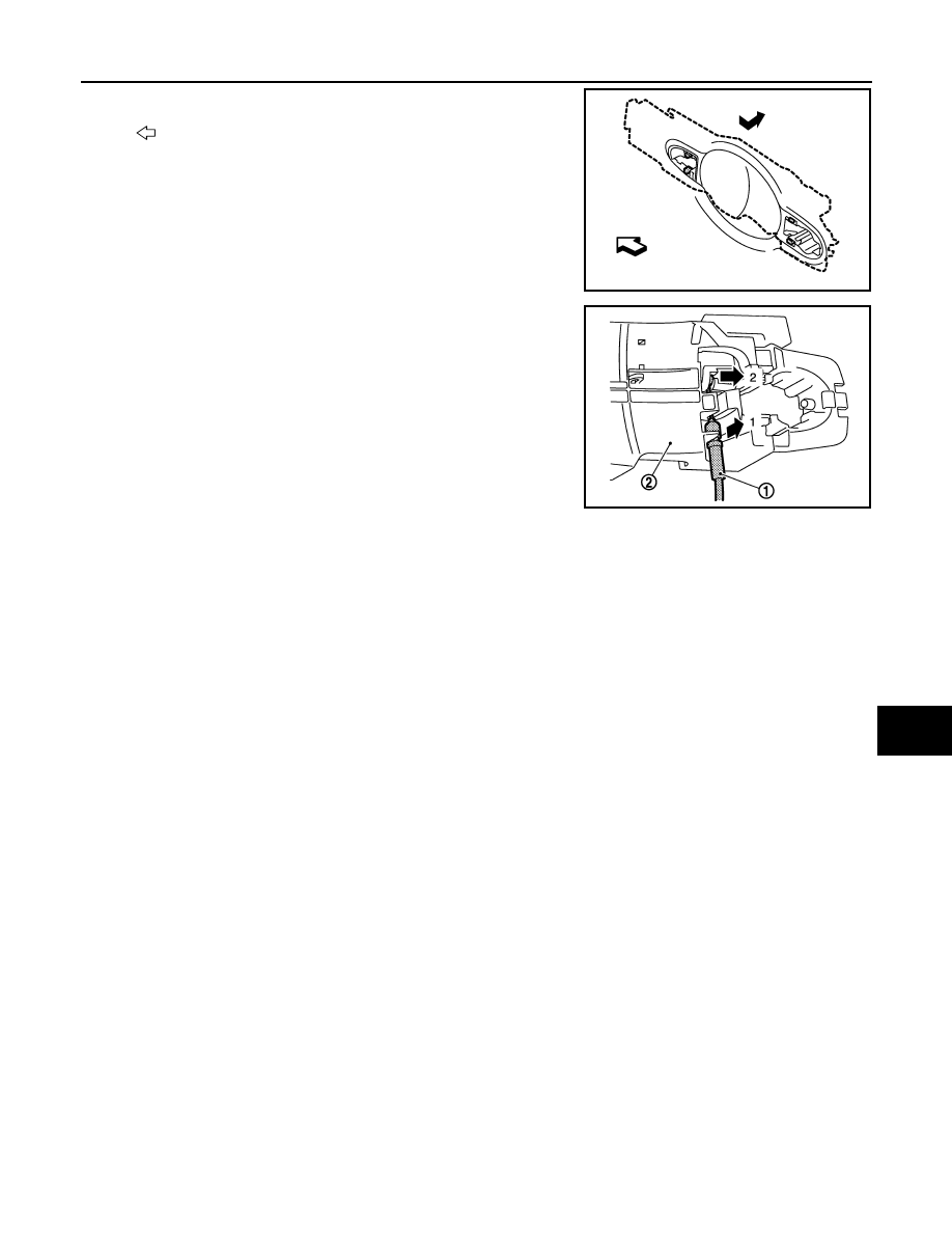
8.
Slide outside handle bracket toward rear of vehicle to remove.
9.
Disconnect outside handle cable (1) from outside handle bracket
(2) according to the numerical order 1
→
2 indicated by arrows as
shown in the figure.
CAUTION:
Never bend the outside handle cable end.
INSTALLATION
Note the following items, and install in the reverse order of removal.
CAUTION:
• Check that door lock cables are normally engaged with inside handle and outside handle.
• After installation, check door open/close, and lock/unlock operation.
: Vehicle front
JMKIA5890ZZ
JMKIA5891ZZ