Qashqai J11. Maintenance - part 8
MA-114
< PERIODIC MAINTENANCE >
ENGINE MAINTENANCE (K9K)
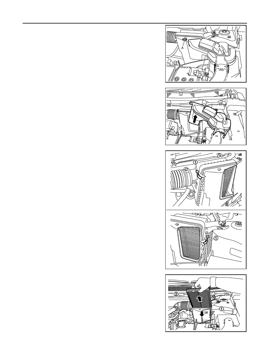
1.
Press the points (A) to separate air resonator from air duct and
air cleaner filter unit.
2.
Remove air resonator following the arrow.
3.
Unhook clips (1) on the air cleaner filter holder.
4.
Separate air cleaner filter holder (1) from air cleaner filter unit
and remove air cleaner filter (2).
E1BIA1002ZZ
E1BIA1003ZZ
E1BIA1004ZZ
E1BIA1005ZZ