Qashqai J11. Maintenance - part 7


  Index      Nissan     Qashqai J11. Maintenance. Service and Repair Manual


Search            copyright infringement  


Content      ..     5      6      7      8     ..


Qashqai J11. Maintenance - part 7


MA-98

< PERIODIC MAINTENANCE >

ENGINE MAINTENANCE (R9M)

ENGINE MAINTENANCE (R9M)

DRIVE BELT

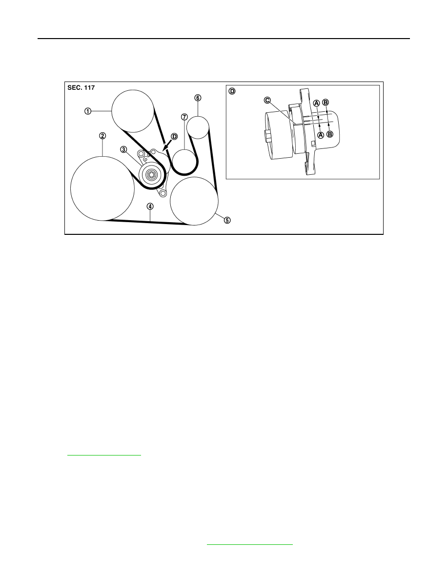
DRIVE BELT : Exploded View

INFOID:0000000010503160

DRIVE BELT : Checking

INFOID:0000000010503161

WARNING:

Be sure to perform this step when the engine is stopped.
• Check that the indicator (C) (notch on fixed side) of drive belt auto-tensioner is within the possible use range

(B).
NOTE:
• Check the drive belt auto-tensioner indication when the engine is cold.
• When new drive belt is installed, the indicator (notch on fixed side) should be within the range (A) in the fig-

ure.

• Visually check entire drive belt for wear, damage or cracks.
• If the indicator (notch on fixed side) is out of the possible use range or belt is damaged, replace drive belt.

CAUTION:

Drive belt auto-tensioner and idler pulley must be replaced with new ones when the drive belt is
replaced.

DRIVE BELT : Tension Adjustment

INFOID:0000000010503162

Refer to 

EM-472, "Drive Belts"

.

DRIVE BELT : Removal and Installation

INFOID:0000000010503163

CAUTION:

• Replace the drive belt that has been removed with a new one.
• Drive belt auto-tensioner and idler pulley must be replaced with new ones when the drive belt is

replaced.

• Never run the engine without the drive belt to avoid damaging the crankshaft pulley.

REMOVAL

1.

Remove front fender protector (RH). Refer to 

EXT-31, "Exploded View"

.

E1BIA1197GB

1.

Water pump

2.

Crankshaft pulley

3.

Drive belt auto-tensioner

4.

Drive belt

5.

A/C compressor or Idler roller

6.

Alternator

7.

Idler pulley

A.

Range when new drive belt is installed

B.

Possible use range

C.

Indicator

D.

View

ENGINE MAINTENANCE (R9M)

MA-99

< PERIODIC MAINTENANCE >

C

D

E

F

G

H

I

J

K

L

M

B

MA

N

O

A

2.

Hold the hexagonal part of drive belt auto-tensioner pulley with a
hexagonal socket (A) securely. Then move the wrench handle in
the direction of arrow (loosening direction of tensioner).

CAUTION:

Never place hand in a location where pinching may occur if
the holding tool accidentally comes off.

3.

Insert a stopper pin (A) in diameter such as short-length screw-
driver into the hole of the retaining boss to fix drive belt auto-ten-
sioner pulley.
• Keep drive belt auto-tensioner pulley arm locked after drive

belt is removed.

NOTE:
Use approximately 3.0 mm (0.118 in) dia. hard metal pin as a
stopper pin.

4.

Remove drive belt. 

INSTALLATION

1.

Install drive belt.

CAUTION:

• Check that drive belt is completely set to pulleys.
• Check for engine oil, working fluid and engine coolant are not adhered to drive belt and each

pulley groove. 

2.

Release drive belt auto-tensioner, and apply tension to drive belt.

3.

Turn crankshaft pulley clockwise several times to equalize tension between each pulley.

4.

Check that the indicator (notch on fixed side) of drive belt auto-tensioner is within the range when new
drive belt is installed. Refer to 

MA-98, "DRIVE BELT : Checking"

.

ENGINE COOLANT

ENGINE COOLANT : Inspection

INFOID:0000000010503164

LEVEL 

• Check if the reservoir tank engine coolant level is within the “MIN”

to “MAX” when the engine is cool.

• Adjust the engine coolant level as necessary.
• Check that the reservoir tank cap is tightened.

WARNING:

Never remove reservoir tank cap when engine is hot. Serious
burns could occur from high-pressure engine coolant escaping
from reservoir tank.

LEAKAGE

E1BIA0658ZZ

E1BIA0657ZZ

E1BIA1145ZZ

MA-100

< PERIODIC MAINTENANCE >

ENGINE MAINTENANCE (MR20DD)

3.

Shifte air cleaner cover  

 to car front side and remove air

cleaner element 

INSTALLATION

Install in the reverse order of removal.
• Insert the projection 

 of air cleaner element 

 in such a way so

that it becomes the position (upper front side of car) of illustration.

• Verify that there is no looseness in air cleaner cover and has been

fixed accurately.

• Check that pawls of air resonator are engaged.

AIR CLEANER FILTER : Inspection (Dry Paper Type)

INFOID:0000000011497306

INSPECTION AFTER REMOVAL

Examine with eyes that there is no stain, clogging, or damage on air cleaner element.
• Remove dusts (such as dead leafs) on air cleaner element surface and inside cleaner case.
• To clean air cleaner element 

, blow air on it from the air intake manifold side 

 to remove trash or dust.

CAUTION:

• When blowing air on the air cleaner element, attach the

cover to the air cleaner case and stay away from the vehicle
as much as possible to prevent the entry of dirt into the air
cleaner case.

• Never blow air from the ambient air side to prevent clogging.

When the ambient air side needs to be cleaned, attach the
cover to the intake manifold side and lightly dust by hand.

• If clogging or damage is observed, replace the air cleaner element.

MAINTENANCE INTERVAL

Refer to 

MA-28, "MR20DD : Periodic Maintenance"

.

AIR CLEANER FILTER : Inspection (Viscous Paper Type)

INFOID:0000000011497307

INSPECTION AFTER REMOVAL

Examine with eyes that there is no stain, clogging, or damage on air cleaner element.
• Remove dusts (such as dead leafs) on air cleaner element surface and inside cleaner case.
• If clogging or damage is observed, replace the air cleaner element.

CAUTION:

Never clean the viscous paper type air cleaner element by blowing as there is a risk of deterioration of
its performance

: Projection

JPBIA6830ZZ

: Projection

JPBIA6830ZZ

Ambient air side

Air blow direction

JSBIA3460ZZ

ENGINE MAINTENANCE (MR20DD)

MA-101

< PERIODIC MAINTENANCE >

C

D

E

F

G

H

I

J

K

L

M

B

MA

N

O

A

MAINTENANCE INTERVAL

Refer to 

MA-28, "MR20DD : Periodic Maintenance"

.

ENGINE OIL

ENGINE OIL : Inspection

INFOID:0000000011497320

ENGINE OIL LEVEL

NOTE:
Before starting engine, put vehicle horizontally and check the engine oil level. If engine is already started, stop
it and allow 10 minutes before checking.
1.

Pull out oil level gauge and wipe it clean.

2.

Insert oil level gauge and check that the engine oil level is within
the range 

 shown in the figure.

3.

If it is out of range, adjust it.

ENGINE OIL APPEARANCE

• Check engine oil for white turbidity or heavy contamination.
• If engine oil becomes turbid and white, it is highly probable that it is contaminated with engine coolant.

Repair or replace damaged parts.

ENGINE OIL LEAKAGE 

Check for engine oil leakage around the following area.
• Oil pan (upper and lower)
• Oil pan drain plug
• Oil pressure sensor
• Oil filter
• Oil cooler
• Intake valve timing control solenoid valve
• Exhaust valve timing control solenoid valve
• Front cover
• VTC cover
• Mating surface between cylinder block and cylinder head
• Mating surface between cylinder head and camshaft bracket
• Mating surface between camshaft bracket and rocker cover
• Mating surface between camshaft bracket and high pressure fuel pump
• Crankshaft oil seals (front and rear)

OIL PRESSURE CHECK

WARNING:

• Be careful not to get burned, as engine oil may be hot.
• When checking engine oil pressure, shift position should be “Parking position”, and apply parking

brake securely.

1.

Check engine oil level.

PBIC3309J

MA-102

< PERIODIC MAINTENANCE >

ENGINE MAINTENANCE (MR20DD)

2.

Disconnect harness connector at oil pressure sensor 

, and

remove oil pressure sensor using a deep socket (commercial
service tool).

CAUTION:

Never drop or shock oil pressure switch.

3.

Install oil pressure gauge [SST: ST25051001] (A) and hose
[SST: ST25052000] (B).

4.

Start engine and warm it up to normal operating temperature.

5.

Check oil pressure with engine running under no-load.
NOTE:
When engine oil temperature is low, engine oil pressure becomes high.

If difference is extreme, check oil passage and oil pump for oil leakage.

6.

After the inspections, install oil pressure switch as follows:

a.

Remove old liquid gasket adhering to oil pressure switch and engine.

b.

Apply liquid gasket and tighten oil pressure switch to specification.
Use Genuine Liquid Gasket or equivalent.

c.

Check engine oil level.

d.

After warming up engine, check that there is no leakage of engine oil with running engine.

ENGINE OIL : Draining

INFOID:0000000011497321

WARNING:

• Be careful not to get burned, as engine oil may be hot.
• Prolonged and repeated contact with used engine oil may cause skin cancer. Try to avoid direct skin

contact with used engine oil. If skin contact is made, wash thoroughly with soap or hand cleaner as
soon as possible. 

1.

Warm up the engine, and check for engine oil leakage from engine components. Refer to 

MA-101,

"ENGINE OIL : Inspection"

.

2.

Stop the engine and wait for 10 minutes.

3.

Loosen oil filler cap.

4.

Remove drain plug and then drain engine oil.

ENGINE OIL : Refilling

INFOID:0000000011497322

1.

Install drain plug with new drain plug washer. Refer to 

EM-303, "Exploded View"

.

: Oil pan (lower)

: Engine front

JSBIA4317ZZ

JPBIA0074ZZ

Engine oil pressure

Refer to 

LU-46, "Engine Oil Pressure"

.

Tightening torque

: Refer to 

EM-369, "Exploded View"

.

ENGINE MAINTENANCE (R9M)

MA-103

< PERIODIC MAINTENANCE >

C

D

E

F

G

H

I

J

K

L

M

B

MA

N

O

A

3.

Disconnect heater hose (1) at position (

) in the figure.

• Enhance heater as high as possible.

4.

Open air relief plug (1). 

5.

Fill reservoir tank with water.
• When engine coolant over flows opened radiator air relief plug, close air relief plug, and continue filling

the engine coolant.

• When engine coolant over flows opened water outlet air relief plug, close air relief plug, and continue fill-

ing the engine coolant.

• When engine coolant over flows disconnected heater hose, connect heater hose, and continue filling the

engine coolant.

6.

Install radiator cap.

7.

Run the engine and warm it up to normal operating temperature.

8.

Rev the engine two or three times under no-load.

9.

Stop the engine and wait until it cools down.

10. Drain water from the system. Refer to 

MA-100, "ENGINE COOLANT : Draining"

.

11. Repeat steps 1 through 10 until clear water begins to drain from radiator.

RESERVOIR TANK CAP

RESERVOIR TANK CAP : Inspection

INFOID:0000000010503168

• Fit the adapter to the reservoir tank cap tester [SST: — (M.S. 554-

07)] (A) as shown.

• When connecting the reservoir tank cap to the reservoir tank cap

tester, apply water or LLC to the reservoir tank cap seal part.

• Check reservoir tank cap relief pressure.

• Replace the reservoir tank cap if the engine coolant passes

through it, or if any fur signs is detected.

CAUTION:

When installing reservoir tank cap, thoroughly wipe out the res-
ervoir tank filler neck to remove any waxy residue or foreign
material.

RADIATOR

: Vehicle front

JPBIA4208ZZ

: Vehicle front

E1BIA1151ZZ

Standard: Refer to 

CO-106, "Radiator"

.

E1BIA0057ZZ

MA-104

< PERIODIC MAINTENANCE >

ENGINE MAINTENANCE (R9M)

RADIATOR : Inspection

INFOID:0000000010503169

Check radiator for mud or clogging. If necessary, clean radiator as follows.

CAUTION:

• Never bend or damage the radiator fins.
• When radiator is cleaned without removal, remove all surrounding parts such as radiator fan, radia-

tor shroud and horns. Then tape the harness and connectors to prevent water from entering.

1.

Apply water by hose to the back side of the radiator core vertically downwards.

2.

Apply water again to all radiator core surface once per minute.

3.

Stop washing if any stains no longer flow out from the radiator.

4.

Blow air into the back side of radiator core vertically downwards.

• Use compressed air lower than 490 kPa (4.9 bar 5 kg/cm

2

, 71psi) and keep distance more than 30 cm (11.8

in). 

5.

 Blow air again into all the radiator core surface once per minute until no water sprays out.

FUEL LINES

FUEL LINES : Inspection

INFOID:0000000010503182

Inspect fuel lines, fuel filler cap, and fuel tank for improper attach-
ment, leakage, cracks, damage, loose connections, chafing or dete-
rioration.

If necessary, repair or replace damaged parts.

FUEL FILTER

A

: Engine

B

: Fuel line

C

:  Fuel  tank

JPBIA0129ZZ

ENGINE MAINTENANCE (MR20DD)

MA-105

< PERIODIC MAINTENANCE >

C

D

E

F

G

H

I

J

K

L

M

B

MA

N

O

A

SPARK PLUG : Exploded View

INFOID:0000000011497310

SPARK PLUG : Removal and Installation

INFOID:0000000011497311

REMOVAL

1.

Remove resonater of air duct assembly. Refer to 

EM-294, "Exploded View"

.

2.

Remove ignition coil. Refer to 

EM-317, "Exploded View"

.

Ignition coil

Spark plug

Rocker cover

Rocker cover gasket

Oil filler cap

PCV valve

O-ring

Comply with the installation proce-
dure when tightening. Refer to 

EM-

317

: Always replace after every disassembly.

: N·m (kg-m, ft-lb)

: N·m (kg-m, in-lb)

JPBIA6815GB

MA-106

< PERIODIC MAINTENANCE >

ENGINE MAINTENANCE (R9M)

FUEL FILTER : Water Draining

INFOID:0000000010503172

1.

Connect drain hose (suitable hose) to the end of drain plug (A).

2.

Prepare a tray at the drain plug open end.

3.

Loosen drain plug, and operate priming bulb to drain water from
fuel filter.

CAUTION:

• Water in filter is drained with fuel. Prepare larger capacity

pan than fuel filter volume.

• Drained water is mixed with fuel. Prevent fuel from adher-

ing to rubber parts such as engine mounting insulator.

4.

After draining, close drain plug by hand.

CAUTION:

If drain plug is tightened excessively, it may be damaged
and fuel will leak. Never use tools to tighten drain plug.

5.

Bleed air in fuel piping. Refer to 

MA-106, "FUEL FILTER : Air Bleeding"

.

6.

Start engine and check there is no fuel leakage.

FUEL FILTER : Air Bleeding

INFOID:0000000010503173

1.

Degassing from the diesel circuit is automatic.

FUEL FILTER : Fuel Filter Sensor (With Fuel Filter Warning)

INFOID:0000000010503174

• Drain water from fuel filter, when the fuel filter warning lamp turns

ON. Refer to 

MA-106, "FUEL FILTER : Water Draining"

.

FUEL FILTER : Inspection

INFOID:0000000010503175

INSPECTION AFTER INSTALLATION

Check that there is no fuel leakage at connections in the following steps.
• Start engine and rev it up and check that there is no fuel leakage at connections.

AIR CLEANER FILTER

AIR CLEANER FILTER : Removal and Installation

INFOID:0000000010503176

REMOVAL

1.

Press the points (A) to separate air resonator from air duct and
air cleaner filter unit.

E1BIA0637ZZ

PBIC2664E

E1BIA1002ZZ

ENGINE MAINTENANCE (R9M)

MA-107

< PERIODIC MAINTENANCE >

C

D

E

F

G

H

I

J

K

L

M

B

MA

N

O

A

2.

Remove air resonator following the arrow.

3.

Unhook clips (1) on the air cleaner filter holder.

4.

Separate air cleaner filter holder (1) from air cleaner filter unit
and remove air cleaner filter (2). 

INSTALLATION

Install in the reverse order of removal.

ENGINE OIL

ENGINE OIL : Inspection

INFOID:0000000010503177

ENGINE OIL LEVEL

NOTE:
Before starting engine, put vehicle horizontally and check that the engine oil level. If engine is already started,
stop it and allow 10 minutes before checking.

1.

Pull out oil level gauge and wipe it clean.

E1BIA1003ZZ

E1BIA1004ZZ

E1BIA1005ZZ

MA-108

< PERIODIC MAINTENANCE >

ENGINE MAINTENANCE (K9K)

3.

Make sure that tension of each belt is within the standard.

DRIVE BELT : Inspection

INFOID:0000000011497392

INSPECTION

WARNING:

Be sure to perform when the engine is stopped.

1.

Inspect drive belt for cracks, fraying, wear and oil. Replace drive belt if necessary.

2.

Manually evaluate the drive belt tension (tension cannot be measured using frequency meter).

3.

Replace drive belt when tension is beyond normal operating limit.

CAUTION:

Auto-tensioner must be replaced with a new one when the belt is replaced.

DRIVE BELT : Adjustment

INFOID:0000000011497393

Belt tensioning is not necessary, as it is automatically adjusted by auto-tensioner.

ENGINE COOLANT

ENGINE COOLANT : Inspection

INFOID:0000000011497408

LEVEL 

• Check if the reservoir tank engine coolant level is within the “MIN”

to “MAX” when the engine is cool.

• Adjust the engine coolant level as necessary.
• Check that the reservoir tank cap is tightened.

WARNING:

Never remove reservoir tank cap when engine is hot. Serious
burns could occur from high-pressure engine coolant escaping
from reservoir tank.

LEAKAGE

• To check for leakage, fit the adapter (B) to the reservoir tank, and

then connect it to the reservoir tank cap tester [SST: — (M.S.554-
07)] (A) as shown.

WARNING:

Never remove reservoir tank cap when engine is hot. Serious
burns could occur from high-pressure engine coolant escap-
ing from reservoir tank.

CAUTION:

Higher test pressure than specified may cause radiator dam-
age.

• If anything is found, repair or replace damaged parts.

ENGINE COOLANT : Draining

INFOID:0000000011497409

WARNING:

• Never remove radiator cap when engine is hot. Serious burns may occur from high-pressure engine

coolant escaping from radiator. 

• Wrap a thick cloth around the radiator cap. Slowly turn it a quarter of a turn to release built-up pres-

sure. Then turn it all the way.

1.

Remove engine under cover.

2.

Remove reservoir tank cap.

E1BIA1145ZZ

Testing pressure: Refer to 

CO-137, "Radiator"

.

E1BIA1147ZZ

ENGINE MAINTENANCE (R9M)

MA-109

< PERIODIC MAINTENANCE >

C

D

E

F

G

H

I

J

K

L

M

B

MA

N

O

A

b.

Check engine oil level.

c.

After warming up engine, check that there is no leakage of engine oil with running engine.

ENGINE OIL : Draining

INFOID:0000000010503178

WARNING:

• Be careful not to get burned, as engine oil may be hot.
• Prolonged and repeated contact with used engine oil may cause skin cancer. Try to avoid direct skin

contact with used engine oil. If skin contact is made, wash thoroughly with soap or hand cleaner as
soon as possible. 

1.

Warm up the engine, and check for engine oil leakage from engine components. Refer to 

MA-107,

"ENGINE OIL : Inspection"

.

2.

Stop the engine and wait for 10 minutes.

3.

Remove engine undercover.

4.

Loosen oil level gauge.

5.

Remove oil pan drain plug (1) using a square driver [8 mm
(0.315 in)]. Drain engine oil.

ENGINE OIL : Refilling

INFOID:0000000010503179

1.

Install drain plug with new washer.

CAUTION:

Be sure to clean drain plug and install with new washer.

2.

Refill with new engine oil.
Engine oil specification and viscosity: Refer to 

MA-59, "Fluids and Lubricants"

.

CAUTION:

• The refill capacity depends on the engine oil temperature and drain time. Use these specifica-

tions for reference only.

• Always use oil level gauge to determine the proper amount of engine oil in the engine.

3.

Warm up engine and check area around drain plug and oil filter body for engine oil leakage.

4.

Stop engine and wait for 10 minutes.

5.

Check the engine oil level. Refer to 

LU-48, "Inspection"

.

6.

Perform "Engine oil data reset". Refer to 

EC9-159, "Work Procedure"

.

OIL FILTER

OIL FILTER : Removal and Installation

INFOID:0000000010503180

REMOVAL

WARNING:

Be careful not to get burned when engine and engine oil may be hot.

CAUTION:

• When removing, prepare a shop cloth to absorb any engine oil leakage or spillage.

: Vehicle front

E1BIA0601ZZ

Tightening torque

: 50 N·m (5.1 Kg-m, 37 ft-lb)

Engine oil capacity

Refer to 

LU-57, "Periodical Maintenance Specification"

.

MA-110

< PERIODIC MAINTENANCE >

ENGINE MAINTENANCE (K9K)

5.

When engine coolant spill from heater hose with continuous
flow, connect heater hose and continue filling reservoir tank until
reach “MAX” level 

6.

7.

Install radiator cap.

8.

Warm up engine at 3000 rpm until thermostat is opened.
• Check thermostat opening condition by touching radiator hose (lower) to see a flow of warm water.

CAUTION:

Watch water temperature gauge so as not to overheat engine.

9.

Stop the engine and cool down to less than approximately 50

°

C (122

°

F).

• Cool down using fan to reduce the time.
• If necessary, refill radiator up to filler neck with engine coolant.

CAUTION:

Never adhere the engine coolant to electronic equipments (alternator etc.).

10. Refill reservoir tank to “MAX” level line with engine coolant.

11. Repeat steps 7 through 10 two or more times with radiator cap installed until engine coolant level no

longer drops. 

12. Check cooling system for leakage with engine running.

13. Warm up the engine, and check for flowing noise while repeat at least three time slow acceleration from

idle up to 3,000 rpm.

14. If flowing noise is heard, bleed air from cooling system by repeating step 7 through 13 until the flowing

noise is longer heard. 

ENGINE COOLANT : Flushing

INFOID:0000000011497411

1.

Install reservoir tank if removed and radiator drain plug (1). 

CAUTION:

Be sure to clean drain plug and install with new O-ring.

A

:  MAX

B

:  MIN

Reservoir tank engine coolant capacity 
(At “MAX” level)

Refer to 

CO-111, "Periodical Maintenance Specifica-

tion"

.

JPBIA0102ZZ

E1BIA1139ZZ

ENGINE MAINTENANCE (K9K)

MA-111

< PERIODIC MAINTENANCE >

C

D

E

F

G

H

I

J

K

L

M

B

MA

N

O

A

2.

Disconnect heater hose (1) at position (

) in the figure.

• Enhance heater as high as possible.

3.

Fill reservoir tank with water.
• When engine coolant over flows disconnected heater hose, connect heater hose, and continue filling the

engine coolant.

4.

Install radiator cap.

5.

Run the engine and warm it up to normal operating temperature.

6.

Rev the engine two or three times under no-load.

7.

Stop the engine and wait until it cools down.

8.

Drain water from the system. Refer to 

MA-108, "ENGINE COOLANT : Draining"

.

9.

Repeat steps 1 through 8 until clear water begins to drain from radiator.

RESERVOIR TANK CAP

RESERVOIR TANK CAP : Inspection

INFOID:0000000011497413

• Fit the adapter to the reservoir tank cap tester [SST: — (M.S. 554-

07)] (A) as shown.

• When connecting the reservoir tank cap to the reservoir tank cap

tester, apply water or LLC to the reservoir tank cap seal part.

• Check reservoir tank cap relief pressure.

• Replace the reservoir tank cap if the engine coolant passes

through it, or if any fur signs is detected.

CAUTION:

When installing reservoir tank cap, thoroughly wipe out the res-
ervoir tank filler neck to remove any waxy residue or foreign
material.

RADIATOR

RADIATOR : Inspection

INFOID:0000000011497415

Check radiator for mud or clogging. If necessary, clean radiator as follows.

CAUTION:

• Never bend or damage the radiator fins.
• When radiator is cleaned without removal, remove all surrounding parts such as radiator fan, radia-

tor shroud and horns. Then tape the harness and connectors to prevent water from entering.

1.

Apply water by hose to the back side of the radiator core vertically downwards.

2.

Apply water again to all radiator core surface once per minute.

3.

Stop washing if any stains no longer flow out from the radiator.

4.

Blow air into the back side of radiator core vertically downwards.

• Use compressed air lower than 490 kPa (4.9 bar 5 kg/cm

2

, 71psi) and keep distance more than 30 cm (11.8

in). 

5.

 Blow air again into all the radiator core surface once per minute until no water sprays out.

FUEL LINES

: Vehicle front

JPBIA4208ZZ

Standard: Refer to 

CO-137, "Radiator"

.

E1BIA0057ZZ

MA-112

< PERIODIC MAINTENANCE >

CHASSIS MAINTENANCE

CHASSIS MAINTENANCE

HEADLAMP AIMING ADJUSTMENT (LED TYPE - LHD)

HEADLAMP AIMING ADJUSTMENT (LED TYPE - LHD) : Aiming Adjustment Proce-
dure

INFOID:0000000010355387

1.

Place the screen.
NOTE:
• Stop the vehicle at the perpendicular angle to the wall.
• Set the screen so that it is perpendicular to a level load surface.

2.

Face the vehicle squarely toward the screen and make the distance between the headlamp center and
the screen 10 m (32.8 ft).

3.

Start the engine and illuminate the headlamp (LO).
NOTE:
Block light from the headlamp that is not being adjusted with a thick fabric or another object, so that it
does not reach the adjustment screen.

CAUTION:

Never cover lens surface with tape, etc. because it is made from plastic.

4.

Use the aiming adjustment screw to adjust the elbow point projected by the low beams on the screen, so
that it is within the aiming adjustment area.
Low beam distribution on the screen

Aiming adjustment area

Elbow point

Headlamp center

H.

Horizontal center line of headlamp

V.

Vertical center line of headlamp

JSLIA0030ZZ

Vertical center line of headlamp H.

Horizontal center line of headlamp

L.

Distance from headlamp center to screen

X.

Aiming adjustment area
(Lateral)

Y.

Aiming adjustment area
(Vertical)

Distance from headlamp center to screen (L)

: 10 m (32.8 ft)

JSLIA0031ZZ

ENGINE MAINTENANCE (K9K)

MA-113

< PERIODIC MAINTENANCE >

C

D

E

F

G

H

I

J

K

L

M

B

MA

N

O

A

3.

Disconnect fuel filter connector.

4.

Remove fuel filter.

INSTALLATION

1.

Note the following, and install in the reverse order of removal.
• After installation, bleed air from fuel line. Refer to 

MA-113, "FUEL FILTER : Air Bleeding"

.

CAUTION:

Never bend or twist the fuel tube during installation and removal.

FUEL FILTER : Water Draining

INFOID:0000000011497418

1.

Connect drain hose (suitable hose) to the end of drain plug (A).

2.

Prepare a tray at the drain plug open end.

3.

Loosen drain plug, and operate priming bulb to drain water from
fuel filter.

CAUTION:

• Water in filter is drained with fuel. Prepare larger capacity

pan than fuel filter volume.

• Drained water is mixed with fuel. Prevent fuel from adher-

ing to rubber parts such as engine mounting insulator.

4.

After draining, close drain plug by hand.

CAUTION:

If drain plug is tightened excessively, it may be damaged
and fuel will leak. Never use tools to tighten drain plug.

5.

Bleed air in fuel piping. Refer to 

MA-113, "FUEL FILTER : Air Bleeding"

.

6.

Start engine and check there is no fuel leakage.

FUEL FILTER : Air Bleeding

INFOID:0000000011497419

1.

Degassing from the diesel circuit is automatic.

FUEL FILTER : Fuel Filter Sensor (With Fuel Filter Warning)

INFOID:0000000011497420

• Drain water from fuel filter, when the fuel filter warning lamp turns

ON. Refer to 

MA-113, "FUEL FILTER : Water Draining"

.

FUEL FILTER : Inspection

INFOID:0000000011497421

INSPECTION AFTER INSTALLATION

Check that there is no fuel leakage at connections in the following steps.
• Start engine and rev it up and check that there is no fuel leakage at connections.

AIR CLEANER FILTER

AIR CLEANER FILTER : Removal and Installation

INFOID:0000000011497394

REMOVAL

E1BIA0637ZZ

PBIC2664E


Content      ..     5      6      7      8     ..