Qashqai J11. General information - part 4


  Index      Nissan     Qashqai J11. General information. Service and Repair Manual


Search            copyright infringement  


Content      ..     2      3      4     


Qashqai J11. General information - part 4


SERVICE INFORMATION FOR ELECTRICAL INCIDENT

GI-47

< BASIC INSPECTION >

C

D

E

F

G

H

I

J

K

L

M

B

GI

N

O

P

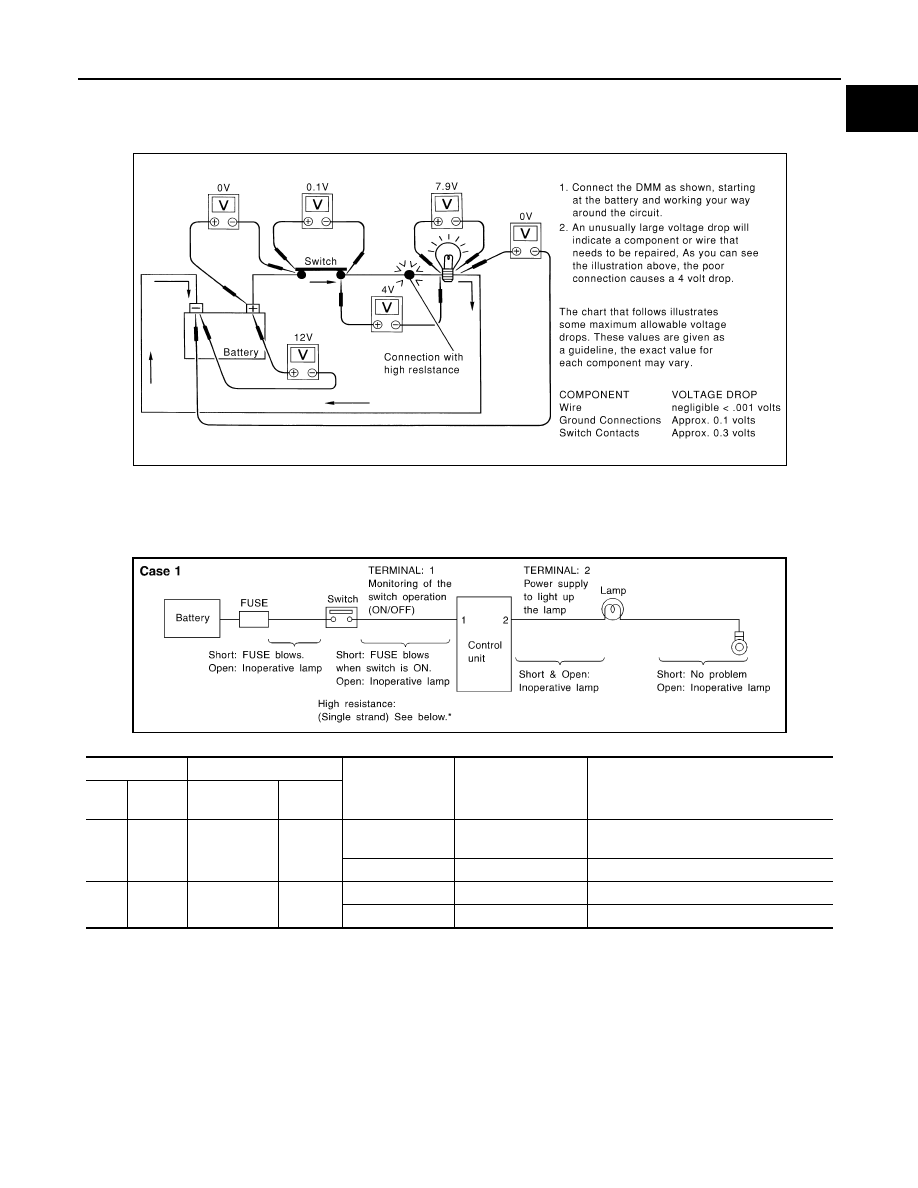
• The (Computer Controlled) system operations can be adversely affected by any variation in resistance in the

system. Such resistance variation may be caused by poor connection, improper installation, improper wire
gauge or corrosion.

• The step by step voltage drop test can identify a component or wire with too much resistance.

CONTROL UNIT CIRCUIT TEST 

System Description
• When the switch is ON, the control unit lights up the lamp.

CASE 1

INPUT-OUTPUT VOLTAGE CHART

• The voltage value is based on the body ground.

• *: If high resistance exists in the switch side circuit (caused by a single strand), terminal 1 does not detect battery voltage. Control unit

does not detect the switch is ON even if the switch does not turn ON. Therefore, the control unit does not supply power to light up the
lamp.

SAIA0258E

Terminal No.

Description

Condition

Value (Approx.)

In case of high resistance such as single 
strand (V) *

+

Signal name

Input/

Output

1

Body 
ground

Switch

Input

Switch ON

Battery voltage

Lower than battery voltage Approx. 8 (Ex-
ample)

Switch OFF

0 V

Approx. 0

2

Body 
ground

Lamp

Output

Switch ON

Battery voltage

Approx. 0 (Inoperative lamp)

Switch OFF

0 V

Approx. 0

MGI034A

GI-48

< BASIC INSPECTION >

SERVICE INFORMATION FOR ELECTRICAL INCIDENT

CASE 2

INPUT-OUTPUT VOLTAGE CHART

• The voltage value is based on the body ground.

• *: If high resistance exists in the switch side circuit (caused by a single strand), terminal 2 does not detect approx. 0 V. Control unit

does not detect the switch is ON even if the switch does not turn ON. Therefore, the control unit does not control ground to light up the
lamp.

Terminal No.

Description

Condition

Value (Approx.)

In case of high resistance such as single 
strand (V) *

+

Signal name

Input/

Output

1

Body 
ground

Lamp

Output

Switch ON

0 V

Battery voltage (Inoperative lamp)

Switch OFF

Battery voltage

Battery voltage

2

Body 
ground

Switch

Input

Switch ON

0 V

Higher than 0 Approx. 4 (Example)

Switch OFF

5 V

Approx. 5

MGI035A

CONSULT/GST CHECKING SYSTEM

GI-49

< BASIC INSPECTION >

C

D

E

F

G

H

I

J

K

L

M

B

GI

N

O

P

CONSULT/GST CHECKING SYSTEM

Description

INFOID:0000000010242497

• When CONSULT/GST is connected with a data link connector (A)

equipped on the vehicle side, it will communicate with the control
unit equipped in the vehicle and then enable various kinds of diag-
nostic tests.

• Refer to CONSULT Software Operation Manual for more informa-

tion.

CONSULT Function and System Application*1

INFOID:0000000010242498

FUNCTION

*: Permanent DTC is not applied for regions where it is not mandated.

SYSTEM APPLICATION

*1

×

: Applicable

1

: Lower instrument panel, driver side

JMAIA1191ZZ

Mode

Function

All DTC Reading

Display all DTCs or diagnostic items that all ECUs are recording and judging.

Work Support

This mode enables a technician to adjust some devices faster and more accurately.

Self Diagnostic Results

Retrieve DTC from ECU and display diagnostic items.

Data Monitor

Monitor the input/output signal of the control unit in real time.

CAN Diagnosis

This mode displays a network diagnosis result about CAN by diagram.

CAN Diagnosis Support Monitor

It monitors the status of CAN communication.

Active Test

Send the drive signal from CONSULT to the actuator. The operation check can be performed.

ECU Identification

Display the ECU identification number (part number etc.) of the selected system.

Function Test

This mode can show results of self-diagnosis of ECU with either “OK” or “NG”. For engines, more 
practical tests regarding sensors/switches and/or actuator are available.

Configuration

Function to READ/WRITE vehicle configuration.

SRT&P-DTC Confirmation

The state of System Readiness Test (SRT) items, the presence or absence of permanent DTC*, 
and driving conditions can be checked.

DTC work support

DTC reproduction procedure can be performed speedily and precisely.

Others

Other results or histories, etc. that are recorded in ECU are displayed.

System

All DTC 

Reading

W

o

rk

 Su

pp

ort

Self

 Dia

g

n

o

s

tic

 Res

u

lt

s

Dat

a

 Monitor

CAN Diagnosis

CAN Diagnosis Support 

Monitor

Active T

e

st

ECU I

d

e

n

ti

ficat

ion

F

u

n

c

ti

on

 T

e

st

Co

nfi

g

u

rat

ion

SR

T&P-DTC Confirmation

DTC work support

Others

ENGINE

x

x

x

x

x

x

x

x

-

x

*4

x

*2*3

x

*3

-

TRANSMISSION 

x

x

x

x

x

x

-

x

-

-

x

*2

-

• CALIB  DATA

IPDM  E/R

x

x

x

x

x

x

x

x

x

x

-

-

-

GI-50

< BASIC INSPECTION >

CONSULT/GST CHECKING SYSTEM

*1: If GST application is equipped, functions in accordance with SAE J1979 and ISO 15031-5 can be used.

*2: Permanent DTC is not applied for regions where it is not mandated.

*3: Used only in models with gasoline engine.

*4: Used only in models with diesel engine.

CONSULT/GST Data Link Connector (DLC) Circuit

INFOID:0000000010242499

INSPECTION PROCEDURE

If the CONSULT/GST cannot diagnose the system properly, check the following items.

NOTE:
The DDL1 and DDL2 circuits from DLC pins 12, 13, 14 and 15 may be connected to more than one system. A
short in a DDL circuit connected to a control unit in one system may affect CONSULT access to other systems.
If the GST cannot operate properly, check the circuit based on the information of SAE J1962 and ISO 15031-
3.

EPS

x

-

x

x

x

-

-

x

-

-

-

-

-

LASER/RADAR

x

x

x

x

x

x

x

x

-

-

-

-

-

HVAC

-

x

x

x

x

x

x

x

-

-

-

-

-

AIR BAG

x

-

x

x

x

-

-

x

-

x

-

-

• TROUBLE DIAG RECORD

CHASSIS  CONTROL

x

-

x

x

x

x

x

x

-

x

-

-

-

BCM

x

x

x

x

x

x

x

x

x

x

-

-

-

LANE  CAMERA

x

x

x

x

x

x

-

x

-

-

-

-

-

TPMS

x

x

x

x

-

-

x

x

-

x

-

-

-

METER  /  M&A

-

x

-

x

x

x

-

-

-

-

-

-

• Warning  History

ABS

x

x

x

x

x

x

x

x

-

x

-

-

-

EHS/PKB

x

x

x

x

x

x

x

x

-

-

-

-

-

SONAR

x

-

x

-

x

x

-

x

-

x

-

-

-

ALL  MODE  AWD/4WD

x

x

x

x

x

x

x

x

-

-

-

-

-

MULTI  AV

x

-

x

x

x

x

-

x

-

x

-

-

-

AVM

x

x

x

x

x

x

x

x

-

x

-

-

-

System

A

ll DTC Reading

W

o

rk Su

pp

ort

Se

lf

 Dia

gno

s

tic

 Res

u

lt

s

Dat

a

 M

o

n

ito

r

CA

N D

iag

no

si

s

CAN Diagnosis Su

ppo

rt M

o

nit

o

r

Ac

ti

ve

 T

e

st

ECU I

d

e

n

ti

ficati

on

Fu

nc

ti

on

 T

e

st

Co

nfi

g

u

rati

o

n

SR

T&

P-DTC Confirmation

DTC work 

support

Others

Symptom

Check item

CONSULT cannot access any 
system.

• CONSULT DLC power supply circuit (Terminal 8 and 16) and ground circuit (Terminal 4 and 5) 

CONSULT cannot access indi-
vidual system. (Other systems 
can be accessed.)

• Power supply and ground circuit for the control unit of the system (For detailed circuit, refer to wiring 

diagram for each system.)

• Open or short circuit between the system and CONSULT DLC (For detailed circuit, refer to wiring 

diagram for each system.)

• Open or short circuit CAN communication line. Refer to 

LAN-24, "Trouble Diagnosis Flow Chart"

.

CONSULT/GST CHECKING SYSTEM

GI-51

< BASIC INSPECTION >

C

D

E

F

G

H

I

J

K

L

M

B

GI

N

O

P

Wiring Diagram - CONSULT/GST CHECKING SYSTEM -

INFOID:0000000010242500

JRAWC0939GB

GI-52

< BASIC INSPECTION >

CONSULT/GST CHECKING SYSTEM

JRAWC1100GB

CONSULT/GST CHECKING SYSTEM

GI-53

< BASIC INSPECTION >

C

D

E

F

G

H

I

J

K

L

M

B

GI

N

O

P

JRAWC1101GB

GI-54

< BASIC INSPECTION >

CONSULT/GST CHECKING SYSTEM

JRAWC0951GB

CONSULT/GST CHECKING SYSTEM

GI-55

< BASIC INSPECTION >

C

D

E

F

G

H

I

J

K

L

M

B

GI

N

O

P

JRAWC0952GB

GI-56

< BASIC INSPECTION >

CONSULT/GST CHECKING SYSTEM

JRAWC0953GB

CONSULT/GST CHECKING SYSTEM

GI-57

< BASIC INSPECTION >

C

D

E

F

G

H

I

J

K

L

M

B

GI

N

O

P

JRAWC0954GB

GI-58

< BASIC INSPECTION >

CONSULT/GST CHECKING SYSTEM

JRAWC0955GB

CONSULT/GST CHECKING SYSTEM

GI-59

< BASIC INSPECTION >

C

D

E

F

G

H

I

J

K

L

M

B

GI

N

O

P

JRAWC0956GB

GI-60

< BASIC INSPECTION >

INSPECTION AND ADJUSTMENT

INSPECTION AND ADJUSTMENT

ADDITIONAL SERVICE WHEN REMOVING BATTERY NEGATIVE TERMINAL

ADDITIONAL SERVICE WHEN REMOVING BATTERY NEGATIVE TERMINAL : Re-
quired Procedure After Battery Disconnection

INFOID:0000000010242501

*

: Not equipped

SYSTEM

ITEM

REFERENCE

Automatic air conditioning system

*

Temperature setting trimmer

Foot position setting trimmer

Inlet port memory function

Inlet port memory function (FRE)

Inlet port memory function (REC)

Gas sensor sensitivity adjustment function

Auto intake switch interlocking movement change

Clean switch interlocking movement change

Automatic drive positioner

*

Automatic drive positioner system

Power window control

Power window control system

PWC-30, "Descrip-

tion"

Sunroof system

*

Sunroof system

Sunshade system

*

Sunshade system

Engine control system (HR)

Throttle valve closed position learning

ECH-105, "Descrip-

tion"

Flywheel learning

ECH-107, "Descrip-

tion"

Rear view monitor

Rear view monitor predictive course line center position adjustment

DAS-101, "Descrip-

tion"

Around view monitor

Predictive course line center position adjustment

AV-180, "CALIBRAT-

ING CAMERA IM-

AGE (AROUND 

VIEW MONITOR) : 

Description"

Automatic back door system

*

Automatic back door system


Content      ..     2      3      4