Index Nissan Qashqai J11. Power control system. Service and Repair Manual
Search copyright infringement
Content .. 2 3 4 5 ..
Qashqai J11. Power control system - part 4
PCS
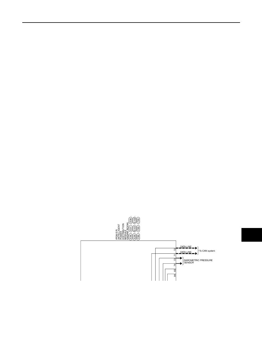
IPDM E/R
PCS-49
< WIRING DIAGRAM >
[IPDM E/R]
C
D
E
F
G
H
I
J
K
L
B
A
O
P
N
JRMWG7376GB