Qashqai J11. Parking brake system - part 2
SYSTEM
PB-17
< SYSTEM DESCRIPTION >
C
D
E
G
H
I
J
K
L
M
A
B
PB
N
O
P
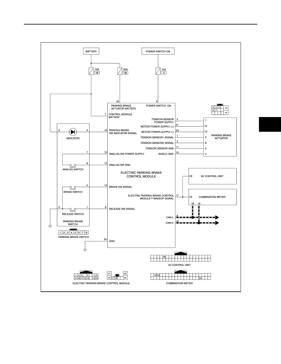
Circuit Diagram
INFOID:0000000010318121
Fail-Safe
INFOID:0000000010318122
• The master warning lamp (yellow) turns ON when a malfunction with the system occurs.
• When parking brake switch is pulled/pushed during system malfunction, electric parking brake indicator
lamp blinks and master warning lamp (red) turns ON when electric parking brake cannot be operated. It
restricts braking and release operations of electric parking brake.
JSFIA1090GB