Qashqai J11. Interior lighting System - part 5


  Index      Nissan     Qashqai J11. Interior lighting System. Service and Repair Manual


Search            copyright infringement  


Content      ..     3      4      5     


Qashqai J11. Interior lighting System - part 5


PUSH-BUTTON IGNITION SWITCH ILLUMINATION CIRCUIT

INL-65

< DTC/CIRCUIT DIAGNOSIS >

C

D

E

F

G

H

I

J

K

M

A

B

INL

N

O

P

NO

>> Repair or replace harnesses.

4.

CHECK PUSH-BUTTON IGNITION SWITCH ILLUMINATION SHORT CIRCUIT

1.

Turn ignition switch OFF.

2.

Disconnect BCM connector and push-button ignition switch connector.

3.

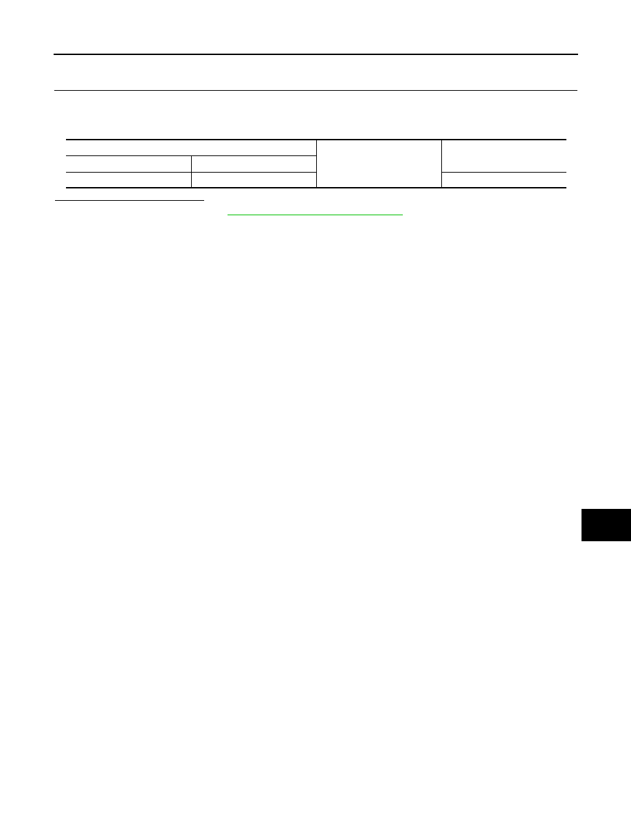
Check continuity between BCM harness connector and ground.

Is the inspection result normal?

YES

>> Replace BCM. Refer to 

BCS-132, "Removal and Installation"

.

NO

>> Repair or replace harnesses.

BCM

Ground

Continuity

Connector

Terminal

M69

88

Not existed

INL-66

< SYMPTOM DIAGNOSIS >

INTERIOR LIGHTING SYSTEM SYMPTOMS

SYMPTOM DIAGNOSIS

INTERIOR LIGHTING SYSTEM SYMPTOMS

Symptom Table

INFOID:0000000010430921

NOTE:
Perform the self-diagnosis with CONSULT before the symptom diagnosis. Perform the trouble diagnosis if any
DTC is detected.

Symptom

Possible cause

Inspection item

All the following lamps do not turn ON.
• Map  lamp
• Room  lamp
• Personal  lamp
• Vanity mirror lamp
• Luggage room lamp
• Spicy illumination

• Fuse
• Harness between battery and interi-

or room lamp relay

• Harness between BCM and interior 

room lamp relay

• Interior room lamp relay
• BCM

Interior room lamp power supply circuit
Refer to 

INL-55, "Diagnosis Proce-

dure"

.

Any of the following lamp does not turn ON.
• Map  lamp
• Room  lamp
• Personal  lamp
• Vanity mirror lamp

• Harness between each interior room 

lamp and interior room lamp relay

• Harness between each interior room 

lamp and ground

• Each interior room lamp

Interior room lamp power supply circuit
Refer to 

INL-57, "Diagnosis Proce-

dure"

.

• Interior room lamp does not turn ON even 

though the door is open.
(It turns ON when turning the interior room 
lamp ON.)

• Interior room lamp does not turn OFF even 

though the door is closed.

• Harness between BCM and each 

door switch

• BCM

Door switch circuit
Refer to 

DLK-94, 

"Component Function Check"

 (Type 

1)*, 

DLK-284, 

"Component Function Check"

 (Type 

2)*, 

DLK-427, 

"Component Function Check"

 (Type 

3)*, 

DLK-567, 

"Component Function Check"

 (Type 

4)*.

• Harness between BCM and each in-

terior room lamp

• BCM

Interior room lamp control circuit
Refer to 

INL-58, "Component Function 

Check"

.

Interior room lamp timer does not activate.
(It turns ON/ OFF when the door opens/clos-
es.)

Check the interior room lamp setting.
Refer to 

INL-15, "INT LAMP : CON-

SULT Function (BCM - INT LAMP)"

.

• Luggage room lamp does not turn ON even 

though the back door is open.

• Luggage room lamp does not turn OFF 

even though the back door is closed.

• Harness between BCM and back 

door switch

• BCM

Back door switch circuit
Refer to 

DLK-94, 

"Component Function Check"

 (Type 

1)*, 

DLK-284, 

"Component Function Check"

 (Type 

2)*, 

DLK-427, 

"Component Function Check"

 (Type 

3)*, 

DLK-567, 

"Component Function Check"

 (Type 

4)*.

• Harness between luggage room 

lamp and interior room lamp relay

• Harness between BCM and luggage 

room lamp

• luggage room lamp
• BCM

Luggage room lamp circuit
Refer to 

INL-60, "Component Function 

Check"

.

INTERIOR LIGHTING SYSTEM SYMPTOMS

INL-67

< SYMPTOM DIAGNOSIS >

C

D

E

F

G

H

I

J

K

M

A

B

INL

N

O

P

*: Refer to 

DLK-24, "Information"

 for detailed vehicle information.

• Spicy illumination does not turn ON even 

though the door is open.

• Spicy illumination does not turn OFF even 

though the door is closed.

• Harness between BCM and each 

door switch

• BCM

Door switch circuit
Refer to 

DLK-94, 

"Component Function Check"

 (Type 

1)*, 

DLK-284, 

"Component Function Check"

 (Type 

2)*, 

DLK-427, 

"Component Function Check"

 (Type 

3)*, 

DLK-567, 

"Component Function Check"

 (Type 

4)*.

• Harness between spicy illumination 

and interior room lamp relay

• Harness between BCM and spicy il-

lumination

• Spicy illumination
• BCM

Spicy illumination circuit
Refer to 

INL-62, "Component Function 

Check"

.

Push-button ignition switch illumination does 
not illuminate.

• Harness between BCM and push-

button ignition switch

• Harness between push-button igni-

tion switch and ground

• Push-button ignition switch
• BCM

Push-button ignition switch illumination 
circuit
Refer to 

INL-64, "Component Function 

Check"

.

Interior room lamp battery saver does not ac-
tivate.

• Harness between BCM and interior 

room lamp relay

• Interior room lamp relay
• BCM

Interior room lamp power supply circuit
Refer to 

INL-55, "Diagnosis Proce-

dure"

.

Symptom

Possible cause

Inspection item

INL-68

< REMOVAL AND INSTALLATION >

MAP LAMP

REMOVAL AND INSTALLATION

MAP LAMP

Exploded View

INFOID:0000000010430922

With sunroof

MAP LAMP

MAP LAMP : Removal and Installation

INFOID:0000000010430923

REMOVAL

CAUTION:

Disconnect the battery negative terminal or remove power circuit fuse when performing the operation
for preventing electric leakage. Refer to 

INL-3, "Precautions for Removing Battery Terminal"

.

JMLIA5183ZZ

Map lamp bracket

Headlining assembly

Map lamp finisher

Lamp housing

Bulb

Lens

: Pawl

: Metal clip

: Vehicle front

MAP LAMP

INL-69

< REMOVAL AND INSTALLATION >

C

D

E

F

G

H

I

J

K

M

A

B

INL

N

O

P

1.

Disengage lens fixing pawls using a remover tool (A), and then
remove lens 

.

CAUTION:

Apply protect tape on remover tool.

2.

Disengage map lamp housing fixing pawl using a remover tool
(A), and then pull out lamp housing 

 according to numerical

order 1

2 indicated by arrows as shown in the figure.

CAUTION:

Apply protect tape on remover tool.

3.

Disconnect map lamp harness connector, and then remove map lamp housing.

INSTALLATION

Install in the reverse order of removal.

MAP LAMP : Replacement

INFOID:0000000010430924

MAP LAMP BULB

CAUTION:

Disconnect the battery negative terminal or remove power circuit fuse when performing the operation
for preventing electric leakage. Refer to 

INL-3, "Precautions for Removing Battery Terminal"

.

1.

Disengage lens fixing pawls using a remover tool (A), and then
remove lens 

.

CAUTION:

Apply protect tape on remover tool.

2.

Remove bulb.

MAP LAMP FINISHER

MAP LAMP FINISHER : Removal and Installation

INFOID:0000000010451298

CAUTION:

Disconnect the battery negative terminal or remove power circuit fuse while performing the operation
to electric leakage. Refer to 

INL-3, "Precautions for Removing Battery Terminal"

.

REMOVAL

: Pawl

JMLIA1063ZZ

: Pawl

JMLIA1064ZZ

: Pawl

JMLIA1063ZZ

INL-70

< REMOVAL AND INSTALLATION >

MAP LAMP

1.

Disengage map lamp assembly fixing pawls and metal clips
according to numerical order 1

3 indicated by arrows as shown

in the figure.

2.

Disconnect harness connectors, and then remove map lamp assenbly.

3.

Remove the following parts after removing map lamp assembly.
• Map lamp: Refer to 

INL-68, "MAP LAMP : Removal and Installation"

.

• Sunshade switch: Refer to 

RF-35, "Removal and Installation"

. (With sunroof)

INSTALLATION

Install in the reverse order of removal.

MAP LAMP BRACKET

MAP LAMP BRACKET : Removal and Installation

INFOID:0000000010430925

REMOVAL

1.

Remove headlining assembly. Refer to 

INT-25, "Removal and Installation"

.

2.

Remove map lamp bracket mounting bolts 

, and then remove

map lamp bracket.

INSTALLATION

Install in the reverse order of removal.

: Pawl

: Metal clip

JMLIA5190ZZ

JMLIA5191ZZ

VANITY MIRROR LAMP

INL-71

< REMOVAL AND INSTALLATION >

C

D

E

F

G

H

I

J

K

M

A

B

INL

N

O

P

VANITY MIRROR LAMP

Exploded View

INFOID:0000000010430926

Replacement

INFOID:0000000010430927

VANITY MIRROR LAMP BULB

CAUTION:

• Disconnect the battery negative terminal or remove power circuit fuse when performing the opera-

tion for preventing electric leakage. Refer to 

INL-3, "Precautions for Removing Battery Terminal"

.

• Never touch the glass surface of the bulb with bare hands or allow oil or grease to get on it for pre-

venting damage to the bulb.

• The surface of the bulb is very hot just after the lamp is turned OFF. Never touch the glass surface of

the bulb with bare hands for preventing burns.

• Leaving the bulb removed from housing for a long period of time can deteriorate performance of the

lens and reflector (due to dirt or clouding). Always prepare a new bulb and have it on hand when
replacing the bulb.

1.

Apply protective tape to vanity mirror of surface for protecting it from damage.

2.

Disengage lens fixing pawls using a remover tool, and then remove lens.

CAUTION:

Use a remover tool wrapped in tape. 

3.

Remove bulb.

Lens

Bulb

Lens

: Pawl

JMLIA5184ZZ

INL-72

< REMOVAL AND INSTALLATION >

GLOVE BOX LAMP

GLOVE BOX LAMP

Exploded View

INFOID:0000000010430928

LHD models

Replacement

INFOID:0000000010430929

GLOVE BOX LAMP BULB

CAUTION:

• Disconnect the battery negative terminal or remove power circuit fuse when performing the opera-

tion for preventing electric leakage. Refer to 

INL-3, "Precautions for Removing Battery Terminal"

.

• Never touch the glass surface of the bulb with bare hands or allow oil or grease to get on it for pre-

venting damage to the bulb.

• The surface of the bulb is very hot just after the lamp is turned OFF. Never touch the glass surface of

the bulb with bare hands for preventing burns.

• Leaving the bulb removed from housing for a long period of time can deteriorate performance of the

lens and reflector (due to dirt or clouding). Always prepare a new bulb and have it on hand when
replacing the bulb.

1.

Remove instrument lower panel LH (RHD models) or RH (LHD models). Refer to 

IP-13, "Removal and

Installation"

.

2.

Remove bulb & socket assembly according to numerical order
1

2 indicated by arrows as shown in the figure.

JMLIA5185ZZ

Lamp housing

Bulb & socket assembly

Instrument lower panel RH

: Pawl

: Vehicle front

JMLIA3624ZZ

SPICY ILLUMINATION

INL-73

< REMOVAL AND INSTALLATION >

C

D

E

F

G

H

I

J

K

M

A

B

INL

N

O

P

SPICY ILLUMINATION

Exploded View

INFOID:0000000010430930

REMOVAL

LHD models

DISASSEMBLY

JMLIA5186ZZ

Console panel assembly LH

Console panel assembly RH

: Pawl

: Metal clip

JMLIA5187ZZ

INL-74

< REMOVAL AND INSTALLATION >

SPICY ILLUMINATION

Replacement

INFOID:0000000010430932

SPICY ILLUMINATION BULB

CAUTION:

• Disconnect the battery negative terminal or remove power circuit fuse when performing the opera-

tion for preventing electric leakage. Refer to 

INL-3, "Precautions for Removing Battery Terminal"

.

• Replacement of a single part is not possible due to the adoption of LED. For replacement, replace

spicy illumination assembly.

1.

Remove console panel assembly. Refer to 

IP-19, "Removal and Installation"

.

2.

Remove console panel mask lid fixing screws 

, and then

remove console panel mask lid.

3.

Remove harness connector fixing clip 

, and then remove spicy

illumination assembly.

Console panel bracket RH

Console panel mask lid RH

Spicy illumination assembly

Console panel RH

: Clip

: Pawl

: Metal clip

: Vehicle front

JMLIA5192ZZ

JMLIA5193ZZ

ROOM LAMP

INL-75

< REMOVAL AND INSTALLATION >

C

D

E

F

G

H

I

J

K

M

A

B

INL

N

O

P

ROOM LAMP

Exploded View

INFOID:0000000010451272

Removal and Installation

INFOID:0000000010451273

CAUTION:

• Disconnect the battery negative terminal or remove power circuit fuse while performing the opera-

tion to electric leakage. Refer to 

INL-3, "Precautions for Removing Battery Terminal"

.

• Never touch the glass surface of the bulb with bare hands or allow oil or grease to get on it to pre-

vent damage to the bulb.

• Never touch the glass surface of the bulb with bare hands because the surface is very hot just after

the lamp is turned OFF to prevent a burns.

• Leaving the bulb removed from housing for a long period of time can deteriorate performance of the

lens and reflector (causing dirty or clouding). Always prepare a new bulb and have it on hand when
replacing the bulb.

REMOVAL

1.

Disengage lens fixing pawls using a remover tool (A), and then
remove lens 

.

CAUTION:

Apply protect tape on remover tool.

Lamp housing

Bulb

Lens

: Pawl

: Vehicle front

JMLIA2093ZZ

: Pawl

JMLIA1230ZZ

INL-76

< REMOVAL AND INSTALLATION >

ROOM LAMP

2.

Disengage lamp housing fixing pawl using a remover tool (A),
and then pull out lamp housing 

 according to numerical order

1

2 indicated by arrows as shown in the figure.

CAUTION:

Apply protect tape on remover tool.

3.

Disconnect harness connector, and then remove lamp housing.

INSTALLATION

Install in the reverse order of removal.

Replacement

INFOID:0000000010451274

CAUTION:

• Disconnect the battery negative terminal or remove power circuit fuse while performing the opera-

tion to electric leakage. Refer to 

INL-3, "Precautions for Removing Battery Terminal"

.

• Never touch the glass surface of the bulb with bare hands or allow oil or grease to get on it to pre-

vent damage to the bulb.

• Never touch the glass surface of the bulb with bare hands because the surface is very hot just after

the lamp is turned OFF to prevent a burns.

• Leaving the bulb removed from housing for a long period of time can deteriorate performance of the

lens and reflector (causing dirty or clouding). Always prepare a new bulb and have it on hand when
replacing the bulb.

ROOM LAMP BULB

1.

Disengage lens fixing pawls using a remover tool (A), and then
remove lens 

.

CAUTION:

Apply protect tape on remover tool.

2.

Remove bulb.

: Pawl

JMLIA1231ZZ

: Pawl

JMLIA1230ZZ

PERSONAL LAMP

INL-77

< REMOVAL AND INSTALLATION >

C

D

E

F

G

H

I

J

K

M

A

B

INL

N

O

P

PERSONAL LAMP

Exploded View

INFOID:0000000010430933

Removal and Installation

INFOID:0000000010430934

REMOVAL

CAUTION:

Disconnect the battery negative terminal or remove power circuit fuse when performing the operation
for preventing electric leakage. Refer to 

INL-3, "Precautions for Removing Battery Terminal"

.

1.

Disengage personal lamp assembly fixing metal clips using a
remover tool (A).

2.

Disconnect harness connector, and then remove personal lamp assembly.

INSTALLATION

Personal lamp base

Bulb

Lens

: Pawl

: Metal clip

: Vehicle front

JMLIA5188ZZ

: Metal clip

JMLIA5194ZZ

INL-78

< REMOVAL AND INSTALLATION >

PERSONAL LAMP

Install in the reverse order of removal.

Replacement

INFOID:0000000010430935

PERSONAL LAMP BULB

CAUTION:

• Disconnect the battery negative terminal or remove power circuit fuse when performing the opera-

tion for preventing electric leakage. Refer to 

INL-3, "Precautions for Removing Battery Terminal"

.

• Never touch the glass surface of the bulb with bare hands or allow oil or grease to get on it for pre-

venting damage to the bulb.

• The surface of the bulb is very hot just after the lamp is turned OFF. Never touch the glass surface of

the bulb with bare hands for preventing burns.

• Leaving the bulb removed from housing for a long period of time can deteriorate performance of the

lens and reflector (due to dirt or clouding). Always prepare a new bulb and have it on hand when
replacing the bulb.

1.

Remove personal lamp assembly. Refer to 

INL-77, "Removal and Installation"

.

2.

Disengage lens fixing pawls using a remover tool, and then
remove lens.

3.

Remove bulb.

: Pawl

JMLIA5195ZZ

LUGGAGE ROOM LAMP

INL-79

< REMOVAL AND INSTALLATION >

C

D

E

F

G

H

I

J

K

M

A

B

INL

N

O

P

LUGGAGE ROOM LAMP

Exploded View

INFOID:0000000010430936

Removal and Installation

INFOID:0000000010430937

REMOVAL

CAUTION:

Disconnect the battery negative terminal or remove power circuit fuse when performing the operation
for preventing electric leakage. Refer to 

INL-3, "Precautions for Removing Battery Terminal"

.

1.

Apply protective tape (A) to rear pillar finisher LH of surface for
protecting it from damage.

Shade

Bulb

Lens

: Pawl

: Vehicle front

JMLIA5189ZZ

JMLIA5196ZZ

INL-80

< REMOVAL AND INSTALLATION >

LUGGAGE ROOM LAMP

2.

Disengage luggage room lamp assembly fixing pawl using a
remover tool (A).

3.

Disconnect harness connector, and then remove luggage room lamp assembly.

INSTALLATION

Install in the reverse order of removal.

Replacement

INFOID:0000000010430938

LUGGAGE ROOM LAMP BULB

CAUTION:

• Disconnect the battery negative terminal or remove power circuit fuse when performing the opera-

tion for preventing electric leakage. Refer to 

INL-3, "Precautions for Removing Battery Terminal"

.

• Never touch the glass surface of the bulb with bare hands or allow oil or grease to get on it for pre-

venting damage to the bulb.

• The surface of the bulb is very hot just after the lamp is turned OFF. Never touch the glass surface of

the bulb with bare hands for preventing burns.

• Leaving the bulb removed from housing for a long period of time can deteriorate performance of the

lens and reflector (due to dirt or clouding). Always prepare a new bulb and have it on hand when
replacing the bulb.

1.

Remove luggage room lamp assembly. Refer to 

INL-79, "Removal and Installation"

.

2.

Remove lens fixing pawls, and then remove lens.

3.

Remove bulb.

: Pawl

JMLIA5197ZZ

: Pawl

JMLIA5247ZZ

SERVICE DATA AND SPECIFICATIONS (SDS)

INL-81

< SERVICE DATA AND SPECIFICATIONS (SDS) 

C

D

E

F

G

H

I

J

K

M

A

B

INL

N

O

P

SERVICE DATA AND SPECIFICATIONS (SDS)

SERVICE DATA AND SPECIFICATIONS (SDS)

bulb specifications

INFOID:0000000010430941

*1

: With Intelligent Key System

*2

: With vanity mirror lamp

*3

: With spicy illumination

*4

: Without sunshade system

*5

: With sunshade system

Item

Type

Wattage (W)

Push-button ignition switch illumination

*1

LED

Map lamp

Wedge

5.0

Vanity mirror lamp

*2

1.2

Glove box lamp

Wedge

1.4

Spicy illumination

*3

LED

Room lamp

*4

Wedge

5.0

Personal lamp

*5

8.0

Luggage room lamp

Wedge

5.0


Content      ..     3      4      5