Index Nissan Qashqai J11. Interior lighting System. Service and Repair Manual
Search copyright infringement
Content .. 2 3 4 5 ..
Qashqai J11. Interior lighting System - part 4
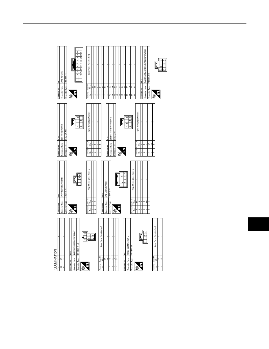
ILLUMINATION
INL-49
< WIRING DIAGRAM >
C
D
E
F
G
H
I
J
K
M
A
B
INL
N
O
P
JRLWD2248GB