Qashqai J11. Heater & Air conditioning System - part 10


  Index      Nissan     Qashqai J11. Heater & Air conditioning System. Service and Repair Manual


Search            copyright infringement  


Content      ..     8      9      10      11     ..


Qashqai J11. Heater & Air conditioning System - part 10


PRECAUTIONS

HA-145

< PRECAUTION >

[TYPE 4]

C

D

E

F

G

H

J

K

L

M

A

B

HA

N

O

P

• The auto acc function is adapted to this vehicle. For this reason, even when the ignition switch is turned

to OFF position, the accessory power source does not turned OFF and continues to be supplied for a
certain amount of time.

6.

Disconnect both battery cables. The steering lock will remain released with both battery cables discon-
nected and the steering wheel can be turned.

7.

Perform the necessary repair operation.

8.

When the repair work is completed, re-connect both battery cables. With the brake pedal released, turn
the ignition switch from OFF position to ON position, then to LOCK position. (The steering wheel will lock
when the ignition switch is turned to LOCK position.)

9.

Perform self-diagnosis check of all control units using CONSULT.

Precaution for Procedure without Cowl Top Cover

INFOID:0000000010704670

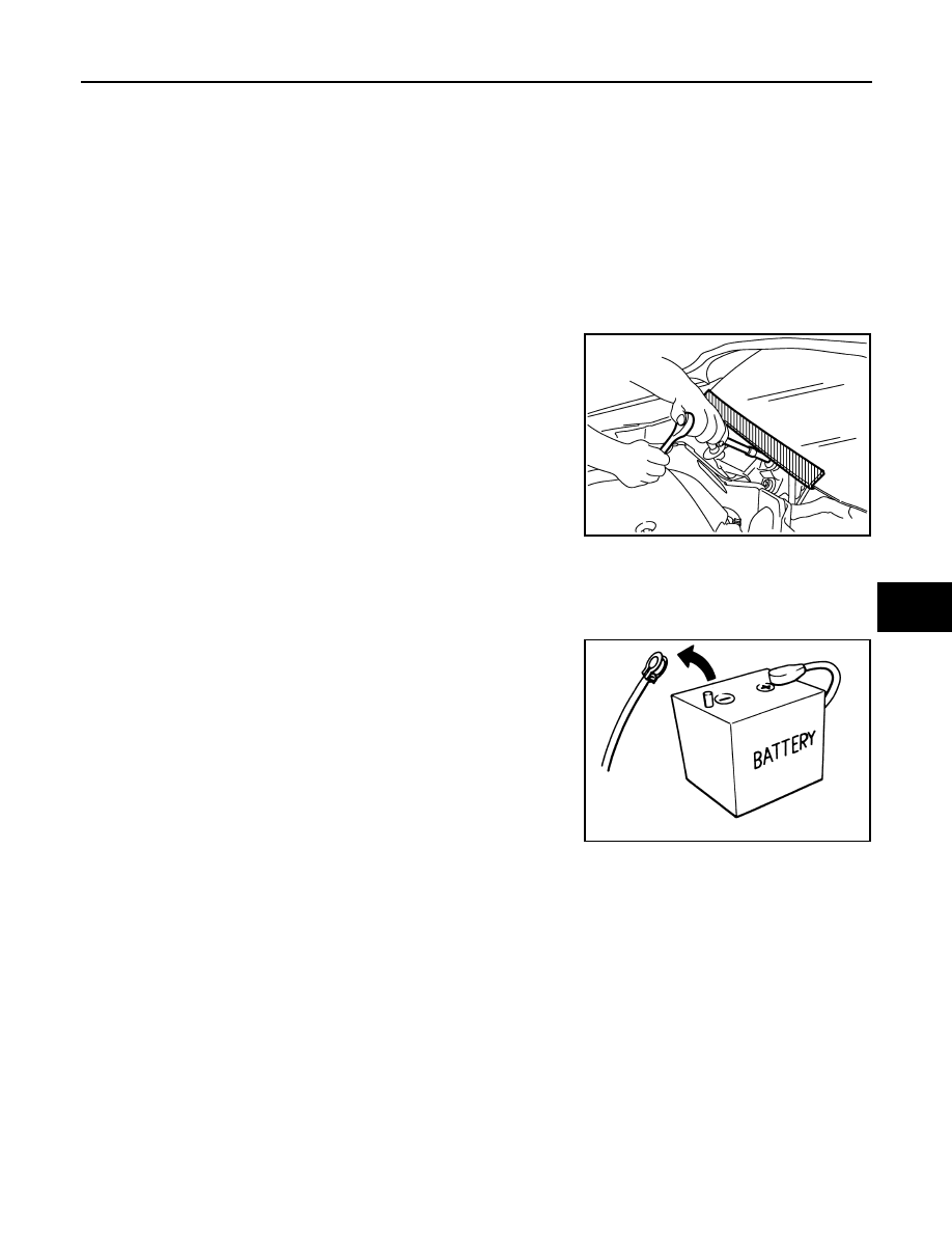
When performing the procedure after removing cowl top cover, cover
the lower end of windshield with urethane, etc to prevent damage to
windshield.

Precautions for Removing Battery Terminal

INFOID:0000000010868428

• With the adoption of Auto ACC function, ACC power is automatically supplied by operating the intelligent key

or remote keyless entry or by opening/closing the driver side door. In addition, ACC power is supplied even
after the ignition switch is turned to the OFF position, i.e. ACC power is supplied for a certain fixed time.

• When disconnecting the 12V battery terminal, turn off the ACC

power before disconnecting the 12V battery terminal, observing
“How to disconnect 12V battery terminal” described below.
NOTE:
Some ECUs operate for a certain fixed time even after ignition
switch is turned OFF and ignition power supply is stopped. If the
battery terminal is disconnected before ECU stops, accidental DTC
detection or ECU data damage may occur.

•  For vehicles with the 2-batteries, be sure to connect the main bat-

tery and the sub battery before turning ON the ignition switch.
NOTE:
If the ignition switch is turned ON with any one of the terminals of
main battery and sub battery disconnected, then DTC may be detected.

•  After installing the 12V battery, always check "Self Diagnosis Result" of all ECUs and erase DTC.

NOTE:
The removal of 12V battery may cause a DTC detection error.

HOW TO DISCONNECT 12V BATTERY TERMINAL

Disconnect 12V battery terminal according to instruction described below.
1.

Open the hood.

2.

Turn ignition switch to the ON position.

3.

Turn ignition switch to the OFF position with the driver side door opened.

4.

Get out of the vehicle and close the driver side door.

5.

Wait at least 3 minutes. For vehicle with the engine listed below, remove the battery terminal after a lapse
of the specified time.

PIIB3706J

SEF289H

D4D engine

: 20 minutes

HRA2DDT

: 12 minutes

K9K engine

: 4 minutes

M9R engine

: 4 minutes

HA-146

< PRECAUTION >

[TYPE 4]

PRECAUTIONS

CAUTION:

While waiting, never operate the vehicle such as locking, opening, and closing doors. Violation of
this caution results in the activation of ACC power supply according to the Auto ACC function.

6.

Remove 12V battery terminal.

CAUTION:

After installing 12V battery, always check self-diagnosis results of all ECUs and erase DTC.

Precautions For Refrigerant System Service

INFOID:0000000010704671

GENERAL REFRIGERANT PRECAUTION

WARNING:

• Never breathe A/C refrigerant and lubricant vapor or mist. Exposure may irritate eyes, nose and

throat. Remove HFC-134a (R-134a) from the A/C system, using certified service equipment meeting
requirements of SAE J-2210 [HFC-134a (R-134a) recycling equipment], or J-2209 [HFC-134a (R-134a)
recovery equipment]. Ventilate work area before resuming service if accidental system discharge
occurs. Additional health and safety information may be obtained from refrigerant and lubricant
manufacturers.

• Never release refrigerant into the air. Use approved recovery/recycling recharging equipment to cap-

ture the refrigerant each time an air conditioning system is discharged.

• Wear always eye and hand protection (goggles and gloves) when working with any refrigerant or air

conditioning system.

• Never store or heat refrigerant containers above 52

°

C (126

°

F).

• Never heat a refrigerant container with an open flame; Place the bottom of the container in a warm

pail of water if container warming is required.

• Never intentionally drop, puncture, or incinerate refrigerant containers.
• Keep refrigerant away from open flames: poisonous gas is produced if refrigerant burns.
• Refrigerant displaces oxygen, therefore be certain to work in well ventilated areas to prevent suffo-

cation.

• Never pressure test or leakage test HFC-134a (R-134a) service equipment and/or vehicle air condi-

tioning systems with compressed air during repair. Some mixtures of air and HFC-134a (R-134a)
have been shown to be combustible at elevated pressures. These mixtures, if ignited, may cause
injury or property damage. Additional health and safety information may be obtained from refriger-
ant manufacturers.

WORKING WITH HFC-134a (R-134a)

CAUTION:

• CFC-12 (R-12) refrigerant and HFC-134a (R-134a) refrigerant are not compatible. Compressor mal-

function is likely to occur if the refrigerants are mixed, refer to “CONTAMINATED REFRIGERANT”
below. To determine the purity of HFC-134a (R-134a) in the vehicle and recovery tank, use Refriger-
ant recovery/recycling recharging equipment and Refrigerant Identifier.

• Use only specified lubricant for the HFC-134a (R-134a) A/C system and HFC-134a (R-134a) compo-

nents. Compressor malfunction is likely to occur if lubricant other than that specified is used.

• The specified HFC-134a (R-134a) lubricant rapidly absorbs moisture from the atmosphere. The fol-

lowing handling precautions must be observed:

- Cap (seal) immediately the component to minimize the entry of moisture from the atmosphere when

removing refrigerant components from a vehicle.

- Never remove the caps (unseal) until just before connecting the components when installing refrig-

erant components to a vehicle. Connect all refrigerant loop components as quickly as possible to
minimize the entry of moisture into system.

- Use only the specified lubricant from a sealed container. Reseal immediately containers of lubricant.

Lubricant becomes moisture saturated and should not be used without proper sealing.

- Never allow lubricant to come in contact with styrene foam parts. Damage may result.

CONTAMINATED REFRIGERANT

Take appropriate steps shown below if a refrigerant other than pure HFC-134a (R-134a) is identified in
a vehicle:
• Explain to the customer that environmental regulations prohibit the release of contaminated refrigerant into

the atmosphere.

R9M engine

: 4 minutes

V9X engine

: 4 minutes

PRECAUTIONS

HA-147

< PRECAUTION >

[TYPE 4]

C

D

E

F

G

H

J

K

L

M

A

B

HA

N

O

P

• Explain that recovery of the contaminated refrigerant could damage service equipment and refrigerant sup-

ply.

• Suggest the customer return the vehicle to the location of previous service where the contamination may

have occurred.

• In case of repairing, recover the refrigerant using only dedicated equipment and containers. Never

recover contaminated refrigerant into the existing service equipment. Contact a local refrigerant prod-
uct retailer for available service if the facility does not have dedicated recovery equipment. This refrigerant
must be disposed of in accordance with all federal and local regulations. In addition, replacement of all
refrigerant system components on the vehicle is recommended.

• The air conditioner warranty is void if the vehicle is within the warranty period. Please contact Nissan Cus-

tomer Affairs for further assistance.

REFRIGERANT CONNECTION

A new type refrigerant connection has been introduced to all refrigerant lines except the following location.
• Expansion valve to evaporator
• Refrigerant pressure sensor to high-pressure pipe 1

WARNING:

Check that all refrigerant is discharged into the recycling equipment and the pressure in the system is
less than atmospheric pressure. Then gradually loosen the discharge side hose fitting and remove it.

CAUTION:

Observe the following when replacing or cleaning refrigerant cycle components.
• Store it in the same way at it is when mounted on the car when the compressor is removed. Failure

to do so will cause lubricant to enter the low-pressure chamber.

• Use always a torque wrench and a back-up wrench when connecting tubes.
• Plug immediately all openings to prevent entry of dust and moisture after disconnecting tubes.
• Connect the pipes at the final stage of the operation when installing an air conditioner in the vehicle.

Never remove the seal caps of pipes and other components until just before required for connection.

• Allow components stored in cool areas to warm to working area temperature before removing seal

caps. This prevents condensation from forming inside A/C components.

• Remove thoroughly moisture from the refrigeration system before charging the refrigerant.
• Replace always used O-rings.
• Apply lubricant to circle of the O-rings shown in illustration when connecting tube. Be careful not to

apply lubricant to threaded portion.

• O-ring must be closely attached to the groove portion of tube.
• Never damage O-ring and tube when replacing the O-ring.
• Connect tube until a click can be heard. Then tighten the nut or bolt by hand. Check that the O-ring is

installed to tube correctly.

• Perform leakage test and make sure that there is no leakage from connections after connecting line.

Disconnect that line and replace the O-ring when the refrigerant leaking point is found. Then tighten
connections of seal seat to the specified torque.

COMPRESSOR

CAUTION:

RHA861F

HA-148

< PRECAUTION >

[TYPE 4]

PRECAUTIONS

• Plug all openings to prevent moisture and foreign matter from entering.
• Store it in the same way at it is when mounted on the car when the compressor is removed.
• Follow “Maintenance of Lubricant Quantity in Compressor” exactly when replacing or repairing

compressor. Refer to 

HA-114, "Description"

.

• Keep friction surfaces between clutch and pulley clean. Wipe it off by using a clean waste cloth

moistened with thinner if the surface is contaminated with lubricant.

• Turn the compressor shaft by hand more than five turns in both directions after compressor service

operation. This distributes equally lubricant inside the compressor. Let the engine idle and operate
the compressor for one hour after the compressor is installed.

• Apply voltage to the new one and check for normal operation after replacing the compressor magnet

clutch.

LEAK DETECTION DYE

CAUTION:

• The A/C system contains a fluorescent leak detection dye used for locating refrigerant leakages. An

ultraviolet (UV) lamp is required to illuminate the dye when inspecting for leakages.

• Wear always fluorescence enhancing UV safety goggles to protect eyes and enhance the visibility of

the fluorescent dye.

• The fluorescent dye leak detector is not a replacement for an electrical leak detector (SST: J-41995).

The fluorescent dye leak detector should be used in conjunction with an electrical leak detector
(SST: J-41995) to pin-point refrigerant leakages.

• Read and follow all manufacture’s operating instructions and precautions prior to performing the

work for the purpose of safety and customer’s satisfaction.

• A compressor shaft seal should not necessarily be repaired because of dye seepage. The compres-

sor shaft seal should only be repaired after confirming the leakage with an electrical leak detector
(SST: J-41995).

• Remove always any remaining dye from the leakage area after repairs are completed to avoid a mis-

diagnosis during a future service.

• Never allow dye to come into contact with painted body panels or interior components. Clean imme-

diately with the approved dye cleaner if dye is spilled. Fluorescent dye left on a surface for an
extended period of time cannot be removed.

• Never spray the fluorescent dye cleaning agent on hot surfaces (engine exhaust manifold, etc.).
• Never use more than one refrigerant dye bottle [1/4 ounce (7.4 cc)] per A/C system.
• Leak detection dyes for HFC-134a (R-134a) and CFC-12 (R-12) A/C systems are different. Never use

HFC-134a (R-134a) leak detection dye in CFC-12 (R-12) A/C system, or CFC-12 (R-12) leak detection
dye in HFC-134a (R-134a) A/C system, or A/C system damage may result.

• The fluorescent properties of the dye remains for three or more years unless a compressor malfunc-

tion occurs.

NOTE:

Identification

• Vehicles with factory installed fluorescent dye have a green label.
• Vehicles without factory installed fluorescent dye have a blue label.

Service Equipment

INFOID:0000000010704672

RECOVERY/RECYCLING RECHARGING EQUIPMENT

Be certain to follow the manufacturer’s instructions for machine operation and machine maintenance. Never
introduce any refrigerant other than that specified into the machine.

ELECTRICAL LEAK DETECTOR

Be certain to follow the manufacturer’s instructions for tester operation and tester maintenance.

VACUUM PUMP

PRECAUTIONS

HA-149

< PRECAUTION >

[TYPE 4]

C

D

E

F

G

H

J

K

L

M

A

B

HA

N

O

P

The lubricant contained inside the vacuum pump is not compatible
with the specified lubricant for HFC-134a (R-134a) A/C systems.
The vent side of the vacuum pump is exposed to atmospheric pres-
sure. So the vacuum pump lubricant may migrate out of the pump
into the service hose. This is possible when the pump is switched
OFF after evacuation (vacuuming) and hose is connected to it.
To prevent this migration, use a manual valve placed near the hose-
to-pump connection, as per the following.
• Vacuum pumps usually have a manual isolator valve as part of the

pump. Close this valve to isolate the service hose from the pump.

• Use a hose equipped with a manual shut-off valve near the pump

end for pumps without an isolator. Close the valve to isolate the
hose from the pump.

• Disconnect the hose from the pump if the hose has an automatic

shut-off valve. As long as the hose is connected, the valve is open
and lubricating oil may migrate.

Some one-way valves open when vacuum is applied and close
under no vacuum condition. Such valves may restrict the pump’s
ability to pull a deep vacuum and are not recommended.

MANIFOLD GAUGE SET

Be certain that the gauge face indicates HFC-134a or R-134a. Be
sure the gauge set has 1/2

-16 ACME threaded connections for ser-

vice hoses. Confirm the set has been used only with refrigerant
HFC-134a (R-134a) and specified lubricants.

SERVICE HOSES

Be certain that the service hoses display the markings described
(colored hose with black stripe). All hoses must equip positive shut-
off devices (either manual or automatic) near the end of the hoses
opposite to the manifold gauge.

SERVICE COUPLERS

RHA270DA

SHA533D

RHA272D

HA-150

< PRECAUTION >

[TYPE 4]

PRECAUTIONS

Never attempt to connect HFC-134a (R-134a) service couplers to
the CFC-12 (R-12) A/C system. The HFC-134a (R-134a) couplers
do not properly connect to the CFC-12 (R-12) system. However, if an
improper connection is attempted, discharging and contamination
may occur.

REFRIGERANT WEIGHT SCALE

Verify that no refrigerant other than HFC-134a (R-134a) and speci-
fied lubricants have been used with the scale. The hose fitting must
be 1/2

-16 ACME if the scale controls refrigerant flow electronically.

CHARGING CYLINDER

Using a charging cylinder is not recommended. Refrigerant may be vented into air from cylinder’s top valve
when filling the cylinder with refrigerant. Also, the accuracy of the cylinder is generally less than that of an
electronic scale or of quality recycle/recharge equipment.

Shut-off valve rotation

A/C service valve

Clockwise

Open

Counterclockwise

Close

RHA273D

RHA274D

PREPARATION

HA-151

< PREPARATION >

[TYPE 4]

C

D

E

F

G

H

J

K

L

M

A

B

HA

N

O

P

PREPARATION

PREPARATION

Special Service Tool

INFOID:0000000010704689

HFC-134a (R-134a) Service Tool and Equipment

• Never mix HFC-134a (R-134a) refrigerant and/or its specified lubricant with CFC-12 (R-12) refrigerant and/

or its lubricant.

• Separate and non-interchangeable service equipment must be used for handling each type of refrigerant/

lubricant.

• Refrigerant container fittings, service hose fittings and service equipment fittings (equipment which handles

refrigerant and/or lubricant) are different between CFC-12 (R-12) and HFC-134a (R-134a). This is to avoid
mixed use of the refrigerants/lubricant.

• Never use adapters that convert one size fitting to another: refrigerant/lubricant contamination occurs and

compressor malfunction may result.

Tool number

(SPX-North America No.)

Tool name

Description

Refrigerant dye leak detection 
kit
Kit includes:
UV lamp and UV safety goggles
HFC-134a (R-134a) dye injector
Use with J-41447, 1/4 ounce 
bottle
HFC-134a (R-134a) fluorescent 
leak detection dye
(Box of 24, 1/4 ounce bottles)
Refrigerant dye cleaner

Power supply:
DC 12 V (Battery terminal)

 UV lamp and UV safety goggles

Power supply:
DC 12 V (Battery terminal)
For checking refrigerant leak when fluores-
cent dye is installed in A/C system
Includes:
UV lamp and UV safety goggles

HFC-134a (R-134a) fluorescent 
leak detection dye
(Box of 24, 1/4 ounce bottles)

Application:
For HFC-134a (R-134a) PAG oil
Container:
1/4 ounce (7.4 cc) bottle
(Includes self-adhesive dye identification 
labels for affixing to vehicle after charging 
system with dye.)

ZHA200H

SHA438F

SHA439F

HA-152

< PREPARATION >

[TYPE 4]

PREPARATION

Commercial Service Tools

INFOID:0000000010704690

HFC-134a (R-134a) Service Tool and Equipment

• Never mix HFC-134a (R-134a) refrigerant and/or its specified lubricant with CFC-12 (R-12) refrigerant and/

or its lubricant.

• Separate and non-interchangeable service equipment must be used for handling each type of refrigerant/

lubricant.

• Refrigerant container fittings, service hose fittings and service equipment fittings (equipment which handles

refrigerant and/or lubricant) are different between CFC-12 (R-12) and HFC-134a (R-134a). This is to avoid
mixed use of the refrigerants/lubricant.

• Never use adapters that convert one size fitting to another: refrigerant/lubricant contamination occurs and

compressor malfunction may result.

HFC-134a (R-134a) dye injector
Use with J-41447, 1/4 ounce 
bottle

For injecting 1/4 ounce of fluorescent leak 
detection dye into A/C system

Refrigerant dye cleaner

For cleaning dye spills

Tool number

(SPX-North America No.)

Tool name

Description

SHA440F

SHA441F

Tool name

Description

Recovery/recycling/recharg-
ing equipment (ACR4)

Function: Refrigerant recovery, recycling 
and recharging

Electrical leak detector

Power supply:
DC 12 V (Cigarette lighter)

RJIA0195E

SHA705EB

PREPARATION

HA-153

< PREPARATION >

[TYPE 4]

C

D

E

F

G

H

J

K

L

M

A

B

HA

N

O

P

Sealant or/and Lubricant

INFOID:0000000010704691

HFC-134a (R-134a) Service Tool and Equipment

• Never mix HFC-134a (R-134a) refrigerant and/or its specified lubricant with CFC-12 (R-12) refrigerant and/

or its lubricant.

• Separate and non-interchangeable service equipment must be used for handling each type of refrigerant/

lubricant.

• Refrigerant container fittings, service hose fittings and service equipment fittings (equipment which handles

refrigerant and/or lubricant) are different between CFC-12 (R-12) and HFC-134a (R-134a). This is to avoid
mixed use of the refrigerants/lubricant.

• Never use adapters that convert one size fitting to another: refrigerant/lubricant contamination occurs and

compressor malfunction may result.

Manifold gauge set (with hos-
es and couplers)

Identification:
• The gauge face indicates HFC-134a (R-

134a).

Fitting size: Thread size

• 1/2

-16 ACME

Service hoses
• High-pressure side hose
• Low-pressure side hose
• Utility hose

Hose color:
• Low-pressure side hose: Blue with black 

stripe

• High-pressure side hose: Red with black 

stripe

• Utility hose: Yellow with black stripe or 

green with black stripe

Hose fitting to gauge:

• 1/2

-16 ACME

Service couplers
• High-pressure side coupler
• Low-pressure side coupler

Hose fitting to service hose:
M14 x 1.5 fitting is optional or permanently 
attached.

Refrigerant weight scale

For measuring of refrigerant
Fitting size: Thread size

1/2

-16 ACME

Vacuum pump
(Including the isolator valve)

Capacity:
• Air displacement: 4 CFM
• Micron rating: 20 microns
• Oil capacity: 482 g (17 oz.)
Fitting size: Thread size

• 1/2

-16 ACME

Tool name

Description

RJIA0196E

S-NT201

S-NT202

S-NT200

S-NT203

HA-154

< PREPARATION >

[TYPE 4]

PREPARATION

Tool name

Description

HFC-134a (R-134a) refrigerant

Container color: Light blue
Container marking: HFC-134a (R-
134a)
Fitting size: Thread size

• Large container 1/2

-16 ACME

ND-OIL8

Type: Polyalkylene glycol oil (PAG), 
ND-OIL8
Application:
HFC-134a (R-134a) swash plate com-
pressors

S-NT196

JMIIA1759ZZ

COMPONENT PARTS

HA-155

< SYSTEM DESCRIPTION >

[TYPE 4]

C

D

E

F

G

H

J

K

L

M

A

B

HA

N

O

P

SYSTEM DESCRIPTION

COMPONENT PARTS

Component Parts Location

INFOID:0000000010867294

Component Description

INFOID:0000000010867295

JMIIA3523ZZ

1.

Refrigerant pressure sensor

2.

Compressor

3.

Condenser

4.

Liquid tank

5.

Expansion valve

6.

Evaporator

A.

Built-in A/C unit assembly

Component

Description

Evaporator

The mist form liquid refrigerant transforms to gas by evaporation by the air conveyed from blower 
motor. The air is cooled by the heat by evaporation.

Condenser

Cools refrigerant discharged from compressor, and transforms it to liquid refrigerant.

Compressor

Intakes, compresses, and discharges refrigerant, to circulate refrigerant inside the refrigerant cycle.

Refrigerant pressure sensor

Refer to 

HAC-19, "Refrigerant Pressure Sensor"

 (AUTOMATIC AIR CONDITIONING SYSTEM) or 

HAC-150, "Refrigerant Pressure Sensor"

 (MANUAL AIR CINDITIONING SYSTEM).

Liquid tank

Eliminates foreign matter in refrigerant, and stores temporarily liquid refrigerant.

Expansion valve

Transforms high-pressure liquid refrigerant to mist form low-pressure liquid refrigerant by drawing 
function.

HA-156

< SYSTEM DESCRIPTION >

[TYPE 4]

SYSTEM

SYSTEM

System Diagram

INFOID:0000000010704693

System Description

INFOID:0000000010704694

REFRIGERANT CYCLE

Refrigerant Flow

The refrigerant from the compressor, flows the condenser with liquid tank, the evaporator, and returns to the
compressor. The refrigerant evaporation in the evaporator is controlled by an expansion valve.

Freeze Protection

To prevent evaporator from freezing up, the evaporator air temperature is monitored, and the voltage signal to
the A/C auto amp. makes the A/C relay go OFF and stop the compressor.

REFRIGERANT SYSTEM PROTECTION

Refrigerant Pressure Sensor

• The refrigerant system is protected against excessively high- or low-pressures by the refrigerant pressure

sensor, located on the condenser & liquid tank assembly. The refrigerant pressure sensor detects the pres-
sure inside the refrigerant line and sends the voltage signal to the ECM if the system pressure rises above,
or falls below the specifications. 

• ECM turns the A/C relay to OFF and stops the compressor when the high-pressure side detected by refriger-

ant pressure sensor is following conditions;

- Approximately 3,120 kPa (31.2 bar, 31.8 kg/cm

2

, 452 psi) or more (Engine speed is 1,500 rpm or more.)

- Approximately 2,740 kPa (27.4 bar, 27.9 kg/cm

2

, 397 psi) or more (Engine speed is less than 1,500 rpm.)

- Approximately 140 kPa (1.4 bar, 1.2 kg/cm

2

, 17 psi) or less

Pressure Relief Valve

The refrigerant system is also protected by a pressure relief valve, located in the rear head of the compressor.
The release port on the pressure relief valve automatically opens and releases refrigerant into the atmosphere
when the pressure of refrigerant in the system increases to an unusual level [more than 3,800 kPa (38.0 bar,
38.8 kg/cm

2

, 551 psi)].

JPIIA1671GB

DIAGNOSIS AND REPAIR WORKFLOW

HA-157

< BASIC INSPECTION >

[TYPE 4]

C

D

E

F

G

H

J

K

L

M

A

B

HA

N

O

P

BASIC INSPECTION

DIAGNOSIS AND REPAIR WORKFLOW

Work Flow

INFOID:0000000010704909

OVERALL SEQUENCE

DETAILED FLOW

1.

INTERVIEW FOR MALFUNCTION

Interview the symptom to the customer.

NNIIA0143GB

HA-158

< BASIC INSPECTION >

[TYPE 4]

DIAGNOSIS AND REPAIR WORKFLOW

>> GO TO 2.

2.

SYMPTOM CHECK

Check the symptom from the customer's information. Check that any symptom occurs other than the inter-
viewed symptom.

Insufficient cooling/Heater>>GO TO 3.
Refrigerant leakage>>GO TO 6.
Noise >> GO TO 7.

3.

CONTROL SYSTEM DIAGNOSIS

Perform the system diagnosis for the A/C control system. Refer to 

HAC-70, "Work Flow"

 (AUTOMATOC AIR

CONDITIONING SYSTEM), 

HAC-186, "Work Flow"

(MANUAL AIR CONDITIONING SYSTEM).

Is A/C control system normal?

YES

>> GO TO 4.

NO

>> GO TO 8.

4.

PERFORMANCE TEST

Perform the performance test. Check the operation of each part. Refer to 

HA-117, "Inspection"

.

>> GO TO 5.

5.

TROUBLE DIAGNOSIS FOR UNUSUAL PRESSURE

Diagnose using a manifold gauge whenever system's high and/or low side pressure(s) is/are unusual. Specify
the malfunctioning part. Refer to 

HA-119, "Symptom Table"

.

Low refrigerant charge>>GO TO 6.
Except above>>GO TO 8.

6.

CHECK REFRIGERANT FOR LEAKAGES

Check refrigerant for leakages. Specify the malfunctioning part. Refer to 

HA-110, "Leak Test"

.

>> GO TO 8.

7.

TROUBLE DIAGNOSIS FOR NOISE

Perform trouble diagnosis for noise. Specify the malfunctioning part. Refer to 

HA-121, "Symptom Table"

.

>> GO TO 8.

8.

MALFUNCTION PART REPAIR

Repair or replace the malfunctioning part.

>> GO TO 9.

9.

REPAIR CHECK (OPERATION CHECK)

Check the operation of each part.

Does it operate normally?

YES

>> INSPECTION END

NO

>> GO TO 2.

REFRIGERANT

HA-159

< BASIC INSPECTION >

[TYPE 4]

C

D

E

F

G

H

J

K

L

M

A

B

HA

N

O

P

REFRIGERANT

Description

INFOID:0000000010704910

CONNECTION OF SERVICE TOOLS AND EQUIPMENT

Leak Test

INFOID:0000000010704911

CHECK REFRIGERANT LEAKAGE USING FLUORESCENT LEAK DETECTION DYE

1.

Install a fender cover (1).

2.

Wear UV safety goggles (2) provided with refrigerant dye leak detection kit.

3.

Connect power cable (4) of UV lamp (6) to positive and negative terminals of the battery (3).

4.

Press UV lamp switch (5) and check A/C system for refrigerant leakage. (Where refrigerant leakage
occurs, fluorescent leak detection dye appears in green color.)

WARNING:

Shut-off valve

A/C service valve

Recovery/recycling/recharging 
equipment

Vacuum pump

Manifold gauge set

Refrigerant container (HFC-134a)

Weight scale

Preferred (best) method

Alternative method

For charging

JSIIA0258ZZ

RJIA3815J

HA-160

< BASIC INSPECTION >

[TYPE 4]

REFRIGERANT

Never look directly into UV lamp light source.
NOTE:
• For continuous operating time of UV lamp, follow the manufacturer operating instructions.
• Illuminate piping joints from different angles using UV lamp and check that there is no leakage.
• Use a mirror in area that is difficult to see to check refrigerant leakage.
• Refrigerant leakage from evaporator can be detected by soaking cotton swab or a similar material with

drain hose water and illuminating it using UV lamp.

• Dust, dirt, and packing materials adhesive used for condenser, evaporator, and other locations may flu-

oresce. Be careful not to misidentify leakage.

5.

Repair or replace parts where refrigerant leakage occurs and wipe off fluorescent leak detection dye.
NOTE:
Completely wipe off fluorescent leak detection dye from gaps between parts, screw threads, and others
using a cotton swab or similar materials.

6.

Use a UV lamp to check that no fluorescent leak detection dye remains after finishing work.

WARNING:

Never look directly into UV lamp light source.
NOTE:
• For continuous operating time of UV lamp, follow the manufacturer operating instructions.
• Dust, dirt, and packing materials adhesive used for condenser, evaporator, and other locations may flu-

oresce. Be careful not to misidentify leakage.

CHECK REFRIGERANT LEAKAGE USING ELECTRICAL LEAK DETECTOR

WARNING:

Never check refrigerant leakage while the engine is running.

CAUTION:

Be careful of the following items so that inaccurate checks or misidentifications are avoided.
• Never allow refrigerant vapor, shop chemical vapors, cigarette smoke, or others around the vehicle.
• Always check refrigerant leakage in a low air flow environment so that refrigerant may not disperse

when leakage occurs.

1.

Stop the engine.

2.

Connect recovery/recycling/recharging equipment or manifold gauge set to A/C service valve.

3.

Check that A/C refrigerant pressure is 345 kPa (3.45 bar, 3.52 kg/cm

2

, 50 psi) or more when temperature

is 16

°

C (61

°

F) or more. When pressure is lower than the specified value, recycle refrigerant completely

and fill refrigerant to the specified level.
NOTE:
Leakages may not be detected if A/C refrigerant pressure is 345 kPa (3.45 bar, 3.52 kg/cm

2

, 50 psi) or

less when temperature is less than 16

°

C (61

°

F).

4.

Clean area where refrigerant leakage check is performed, and check refrigerant leakage along all sur-
faces of pipe connections and A/C system components using electrical leak detector probe.

CAUTION:

• Continue checking when a leakage is found. Always continue and complete checking along all

pipe connections and A/C system components for additional leakage.

• When a leakage is detected, clean leakage area using compressed air and check again.
• When checking leakage of cooling unit inside, always clean inside of drain hose so that the

probe surface may not be exposed to water or dirt.

NOTE:
• Always check leakage starting from high-pressure side and continue to low-pressure side.
• When checking leakage of cooling unit inside, operate blower fan motor for 15 minutes or more at the

maximum fan speed while the engine is stopped, and then insert electrical leak detector probe into drain
hose and hold for 10 minutes or more.

• When disconnecting shut-off valve that is connected to A/C service valve, always evacuate remaining

refrigerant so that misidentification can be avoided.

5.

Repair or replace parts where refrigerant leakage is detected. (Leakage is detected but leakage area is
unknown. GO TO 6.)

6.

Start the engine and set A/C control in the following conditions.
• A/C switch ON
• Air flow: VENT (ventilation)
• Intake door position: Recirculation


Content      ..     8      9      10      11     ..