Qashqai J11. Glass & Window System - part 2
SIDE WINDOW GLASS
GW-17
< REMOVAL AND INSTALLATION >
C
D
E
F
G
H
I
J
L
M
A
B
GW
N
O
P
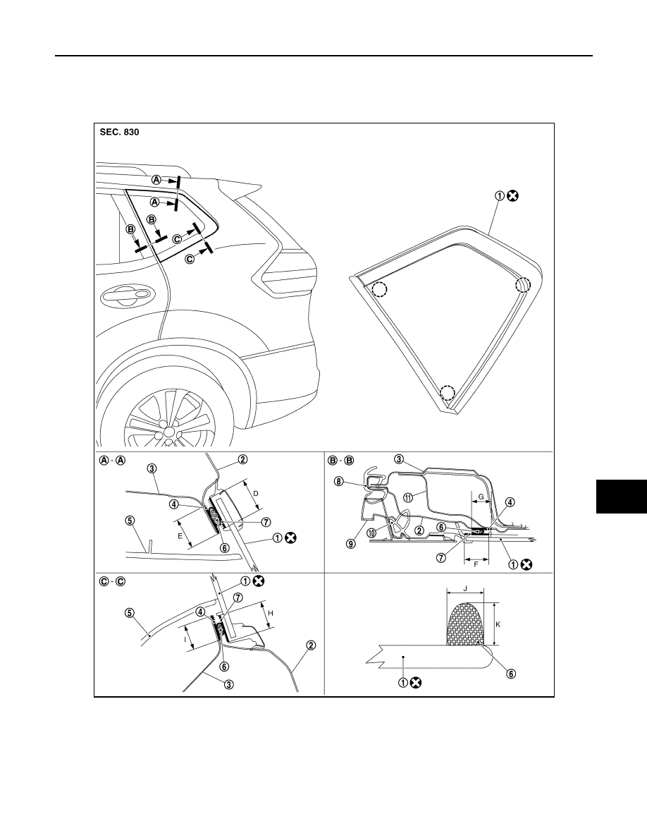
SIDE WINDOW GLASS
Exploded View
INFOID:0000000010478437
1.
Side window glass
2.
Body side outer panel
3.
Rear pillar inner panel
4.
Painted surface for primer
5.
Luggage side upper finisher
6.
Sealant
7.
Glass for primer
8.
Rear body side welt
9.
Rear door sash
10.
11.
Rear pillar inner reinforcement D.
17 mm (0.67 in)
E.
16 mm (0.63 in)
F.
17 mm (0.67 in)
G.
16 mm (0.63 in)
H.
17 mm (0.67 in)
I.
16 mm (0.63 in)
J.
7 mm (0.28 in)
JMKIB3124ZZ