Qashqai J11. Exterior Lighting system - part 19


  Index      Nissan     Qashqai J11. Exterior Lighting system. Service and Repair Manual


Search            copyright infringement  


Content      ..     17      18      19      20     ..


Qashqai J11. Exterior Lighting system - part 19


EXL-290

< DTC/CIRCUIT DIAGNOSIS >

[HALOGEN HEADLAMP]

REAR FOG LAMP CIRCUIT

REAR FOG LAMP CIRCUIT

Component Function Check

INFOID:0000000010469989

1.

CHECK REAR FOG LAMP OPERATION

With CONSULT

1.

Select “HEAD LAMP” of “BCM” using CONSULT.

2.

Select “RR FOG LAMP” in “Active Test” mode.

3.

With operating the test items, check that the rear fog lamp is turned ON.

Is the inspection result normal?

YES

>> Rear fog lamp circuit is normal.

NO

>> Refer to 

EXL-290, "Diagnosis Procedure"

.

Diagnosis Procedure

INFOID:0000000010469990

1.

CHECK REAR FOG LAMP OUTPUT VOLTAGE

With CONSULT

1.

Turn ignition switch OFF.

2.

Disconnect rear fog lamp connector. 

3.

Turn ignition switch ON.

4.

Select “HEAD LAMP” of “BCM” using CONSULT.

5.

Select “RR FOG LAMP” in “Active Test” mode.

6.

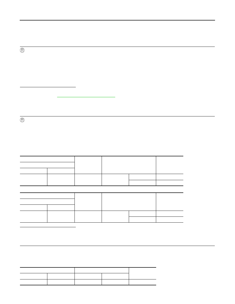
With operating the test items, check voltage between rear fog lamp harness connector and ground.

LHD models

RHD models

Is the inspection result normal?

YES

>> GO TO 4.

NO

>> GO TO 2.

2.

CHECK REAR FOG LAMP POWER SUPPLY CIRCUIT (OPEN)

1.

Turn ignition switch OFF.

2.

Disconnect BCM connector. 

3.

Check continuity between BCM harness connector and rear fog lamp harness connector. 

LHD models

On

: Rear fog lamp ON

Off

: Rear fog lamp OFF

+

-

Test item

Voltage

Rear fog lamp

Connector

Terminal

B24

1

Ground

RR FOG LAMP

On

9 – 16 V

Off

0 V

+

-

Test item

Voltage

Rear fog lamp

Connector

Terminal

D83

1

Ground

RR FOG LAMP

On

9 – 16 V

Off

0 V

BCM

Rear fog lamp

Continuity

Connector

Terminal

Connector

Terminal

B3

122

B24

1

Existed

REAR FOG LAMP CIRCUIT

EXL-291

< DTC/CIRCUIT DIAGNOSIS >

[HALOGEN HEADLAMP]

C

D

E

F

G

H

I

J

K

M

A

B

EXL

N

O

P

RHD models

Is the inspection result normal?

YES

>> GO TO 3.

NO

>> Repair or replace harness.

3.

CHECK REAR FOG LAMP POWER SUPPLY CIRCUIT (SHORT)

Check continuity between BCM harness connector and ground.

Is the inspection result normal?

YES

>> Replace BCM. Refer to 

BCS-132, "Removal and Installation"

.

NO

>> Repair or replace harness.

4.

CHECK REAR FOG LAMP GROUND CIRCUIT

1.

Turn ignition switch OFF.

2.

Check continuity between rear fog lamp harness connector and ground. 

LHD models

LHD models

Is the inspection result normal?

YES

>> GO TO 5.

NO

>> Repair or replace harness.

5.

CHECK REAR FOG LAMP BULB

Check rear fog lamp bulb.

Is the inspection result normal?

YES

>> Check rear fog lamp bulb socket. Repair or replace if necessary.

NO

>> Replace rear fog lamp bulb. Refer to 

EXL-331, "Replacement"

.

BCM

Rear fog lamp

Continuity

Connector

Terminal

Connector

Terminal

B3

122

D83

1

Existed

BCM

Continuity

Connector

Terminal

B3

122

Ground

Not existed

Rear fog lamp

Continuity

Connector

Terminal

B24

2

Ground

Existed

Rear fog lamp

Continuity

Connector

Terminal

D83

2

Ground

Existed

EXL-292

< DTC/CIRCUIT DIAGNOSIS >

[HALOGEN HEADLAMP]

TURN SIGNAL LAMP CIRCUIT

TURN SIGNAL LAMP CIRCUIT

Component Function Check

INFOID:0000000010469992

1.

CHECK TURN SIGNAL LAMP OPERATION

1.

Turn ignition switch ON.

2.

With operating the turn signal switch, check that the turn signal lamp is blinks.

Is the inspection result normal?

YES

>> Turn signal lamp circuit is normal.

NO

>> Refer to 

EXL-292, "Diagnosis Procedure"

.

Diagnosis Procedure

INFOID:0000000010469993

1.

CHECK SYMPTOM

Check symptom (A or B)

Which symptom is detected?

A

>> GO  TO  2.

B

>> GO  TO  4.

2.

CHECK FUSE

1.

Turn ignition switch OFF.

2.

Check that the following fuse is not fusing.

Is the inspection result normal?

YES

>> GO TO 3.

NO

>> Replace the blown fuse after repairing the affected circuit if a fuse is blown.

3.

CHECK BCM POWER SUPPLY (TURN SIGNAL LAMP)

1.

Disconnect BCM connector.

2.

Check voltage between BCM harness connector and ground.

Is the inspection result normal?

YES

>> Replace BCM. Refer to 

BCS-132, "Removal and Installation"

.

NO

>> Repair or replace harness.

4.

CHECK TURN SIGNAL LAMP OUTPUT VOLTAGE

1.

Turn ignition switch OFF.

2.

Disconnect the following connectors.

-

Front combination lamp

Right

: Turn signal lamps RH blink

Left

: Turn signal lamps LH blink

Center

: Turn signal lamps OFF

Symptom

A

All of turn signal lamp are not blinks

B

Applicable side performs high flasher activation

Unit

Location

Fuse No.

Capacity

BCM

Fuse block (J/B)

#33

10 A

+

-

Voltage

BCM

Connector

Terminal

M68

144

Ground

9 – 16 V

TURN SIGNAL LAMP CIRCUIT

EXL-293

< DTC/CIRCUIT DIAGNOSIS >

[HALOGEN HEADLAMP]

C

D

E

F

G

H

I

J

K

M

A

B

EXL

N

O

P

-

Door mirror

-

Rear turn signal lamp

3.

Turn ignition switch ON.

4.

With operating the turn signal switch, check voltage between BCM harness connector and ground.

Front turn signal lamp

Side turn signal lamp

+

-

Test item

Voltage

(Approx.)

BCM

Connector

Terminal

RH

E60

168

Ground

Turn signal 
switch

Right

Center

0 V

LH

167

Left

Center

0 V

+

-

Test item

Voltage

(Approx.)

BCM

Connector

Terminal

RH

M70

43

Ground

Turn signal 
switch

Right

Center

0 V

LH

42

Left

Center

0 V

PKID0926E

PKID0926E

PKID0926E

PKID0926E

EXL-294

< DTC/CIRCUIT DIAGNOSIS >

[HALOGEN HEADLAMP]

TURN SIGNAL LAMP CIRCUIT

Rear turn signal lamp

Is the inspection result normal?

YES

>> GO TO 6.

NO

>> GO TO 5.

5.

CHECK TURN SIGNAL LAMP POWER SUPPLY CIRCUIT (SHORT)

1.

Turn ignition switch OFF.

2.

Disconnect BCM connector.

3.

Check continuity between BCM harness connector and ground.

Front turn signal lamp

Side turn signal lamp

Rear turn signal lamp

Is the inspection result normal?

YES

>> Replace BCM. Refer to 

BCS-132, "Removal and Installation"

.

NO

>> Repair or replace harness.

6.

CHECK TURN SIGNAL LAMP POWER SUPPLY CIRCUIT (OPEN)

1.

Turn ignition switch OFF.

2.

Disconnect BCM connector.

+

-

Test  item

Voltage

(Approx.)

BCM

Connector

Terminal

RH

B3

136

Ground

Turn signal 
switch

Right

Center

0 V

LH

133

Left

Center

0 V

PKID0926E

PKID0926E

BCM

Continuity

Connector

Terminal

RH

E60

168

Ground

Not existed

LH

167

BCM

Continuity

Connector

Terminal

RH

M70

43

Ground

Not existed

LH

42

BCM

Continuity

Connector

Terminal

RH

B3

136

Ground

Not existed

LH

133

TURN SIGNAL LAMP CIRCUIT

EXL-295

< DTC/CIRCUIT DIAGNOSIS >

[HALOGEN HEADLAMP]

C

D

E

F

G

H

I

J

K

M

A

B

EXL

N

O

P

3.

Check continuity between BCM harness connector and each turn signal lamp harness connector.

Front turn signal lamp

Side turn signal lamp (LHD models)

Side turn signal lamp (RHD models)

Rear turn signal lamp

Is the inspection result normal?

YES

>> GO TO 7.

NO

>> Repair or replace harness.

7.

CHECK TURN SIGNAL LAMP GROUND CIRCUIT

Check continuity between each turn signal lamp harness connector and ground.

Front turn signal lamp

Side turn signal lamp (LHD models)

Side turn signal lamp (RHD models)

BCM

Front combination lamp

Continuity

Connector

Terminal

Connector

Terminal

 RH

E60

168

E92

6

Existed

 LH

167

E90

BCM

Door mirror

Continuity

Connector

Terminal

Connector

Terminal

 RH

M70

43

D27

13

Existed

 LH

42

D3

BCM

Door mirror

Continuity

Connector

Terminal

Connector

Terminal

 RH

M70

43

D40

13

Existed

 LH

42

D16

BCM

Rear turn signal lamp

Continuity

Connector

Terminal

Connector

Terminal

 RH

B3

136

B80

1

Existed

 LH

133

B23

Front combination lamp

Continuity

Connector

Terminal

 RH

E92

1

Ground

Existed

 LH

E90

Door mirror

Continuity

Connector

Terminal

 RH

D27

14

Ground

Existed

 LH

D3

Door mirror

Continuity

Connector

Terminal

 RH

D40

14

Ground

Existed

 LH

D16

EXL-296

< DTC/CIRCUIT DIAGNOSIS >

[HALOGEN HEADLAMP]

TURN SIGNAL LAMP CIRCUIT

Rear turn signal lamp

Is the inspection result normal?

YES-1 >> Front turn signal lamp or rear turn signal lamp: GO TO 8.
YES-2 >> Side turn signal lamp: Replace side turn signal lamp. Refer to 

EXL-323, "Removal and Installa-

tion"

.

NO

>> Repair or replace harness.

8.

CHECK TURN SIGNAL LAMP BULB

Check the applicable turn signal lamp bulb.

Is the inspection result normal?

YES

>> Check the corresponding turn signal lamp bulb socket. Repair or replace if necessary.

NO

>> Replace the corresponding turn signal lamp bulb. Refer to 

EXL-319, "Replacement"

 (front turn

signal lamp) or 

EXL-331, "Replacement"

 (rear turn signal lamp).

Rear turn signal lamp

Continuity

Connector

Terminal

 RH

B80

2

Ground

Existed

 LH

B23

LIGHT & RAIN SENSOR

EXL-297

< DTC/CIRCUIT DIAGNOSIS >

[HALOGEN HEADLAMP]

C

D

E

F

G

H

I

J

K

M

A

B

EXL

N

O

P

LIGHT & RAIN SENSOR

Component Function Check

INFOID:0000000010469994

1.

CHECK LIGHT & RAIN SENSOR

1.

Clean light & rain sensor detection area of windshield fully.

2.

Turn ignition switch ON.

3.

Turn lighting switch AUTO.

4.

With the light & rain sensor illuminating, check the auto light function. 

Is the inspection result normal?

YES

>> Light & rain sensor is normal.

NO

>> Refer to 

EXL-297, "Diagnosis Procedure"

.

Diagnosis Procedure

INFOID:0000000010469995

1.

CHECK LIGHT & RAIN SENSOR POWER SUPPLY

1.

Turn ignition switch OFF

2.

Disconnect light & rain sensor connector.

3.

Turn ignition switch ON.

4.

Check voltage between light & rain sensor harness connector and ground.

Is the inspection result normal?

YES

>> GO TO 3.

NO

>> GO TO 2.

2.

CHECK LIGHT & RAIN SENSOR POWER SUPPLY CIRCUIT

1.

Turn ignition switch OFF.

2.

Remove room lamp relay.

3.

Check continuity between room lamp relay harness connector and light & rain sensor harness connector.

Is the inspection result normal?

YES

>> Perform the interior room lamp power supply circuit diagnosis. Refer to 

INL-55, "Diagnosis Proce-

dure"

.

NO

>> Repair or replace harness.

3.

CHECK LIGHT & RAIN SENSOR GROUND CIRCUIT

Check continuity between light & rain sensor harness connector and ground.

Condition

Auto light function

Light & rain sensor

When illuminating

Not operating

When shutting off light

Operating

+

-

Voltage

Light & rain sensor

Connector

Terminal

R5

1

Ground Battery 

voltage

Room lamp relay

Light & rain sensor

Continuity

Connector

Terminal

Connector

Terminal

M80

7

R5

1

Existed

Light & rain sensor

Continuity

Connector

Terminal

R5

3

Ground

Existed

EXL-298

< DTC/CIRCUIT DIAGNOSIS >

[HALOGEN HEADLAMP]

LIGHT & RAIN SENSOR

Is the inspection result normal?

YES

>> GO TO 4.

NO

>> Repair or replace harness.

4.

CHECK LIGHT & RAIN SENSOR SIGNAL

1.

Connect light & rain sensor connector.

2.

Turn ignition switch ON.

3.

Check voltage between BCM harness connector and ground.

Is the inspection result normal?

YES

>> Replace light & rain sensor. Refer to 

EXL-327, "Removal and Installation"

.

NO

>> GO TO 5.

5.

CHECK LIGHT & RAIN SENSOR SIGNAL CIRCUIT (OPEN)

1.

Turn ignition switch OFF.

2.

Disconnect BCM connector and light & rain sensor connector.

3.

Check continuity between BCM harness connector and light & rain sensor harness connector.

Is the inspection result normal?

YES

>> GO TO 6.

NO

>> Repair or replace harness.

6.

CHECK LIGHT & RAIN SENSOR SIGNAL CIRCUIT (SHORT)

Check continuity between BCM harness connector and ground.

Is the inspection result normal?

YES

>> Replace BCM. Refer to 

BCS-132, "Removal and Installation"

.

NO

>> Repair or replace harness.

+

-

Condition

Voltage

(Approx.)

BCM

Connector

Terminal

M70

47

Ground 

Ignition switch 
ON

8.7V

JPMIA0156GB

BCM

Light & rain sensor

Continuity

Connector

Terminal

Connector

Terminal

M70

47

R5

2

Existed

BCM

Continuity

Connector

Terminal

M70

47

Ground

Not existed

HAZARD SWITCH

EXL-299

< DTC/CIRCUIT DIAGNOSIS >

[HALOGEN HEADLAMP]

C

D

E

F

G

H

I

J

K

M

A

B

EXL

N

O

P

HAZARD SWITCH

Component Function Check

INFOID:0000000010469997

1.

CHECK HAZARD SWITCH SIGNAL

With CONSULT

1.

Turn ignition switch ON.

2.

Select “FLASHER” of “BCM” using CONSULT.

3.

Select “HAZARD SW” in “Data Monitor” mode.

4.

With operating the hazard switch, check the monitor status.

Is the inspection result normal?

YES

>> Hazard switch circuit is normal.

NO

>> Refer to 

EXL-299, "Diagnosis Procedure"

.

Diagnosis Procedure

INFOID:0000000010469998

1.

CHECK HAZARD SWITCH SIGNAL

1.

Turn ignition switch OFF.

2.

Disconnect hazard switch connector.

3.

Check voltage between hazard switch connector and ground.

Is the inspection result normal?

YES

>> GO TO 4.

NO

>> GO TO 2.

2.

CHECK HAZARD SWITCH SIGNAL CIRCUIT (OPEN)

1.

Disconnect BCM connector.

2.

Check continuity between hazard switch harness connector and BCM harness connector.

Is the inspection result normal?

YES

>> GO TO 3.

NO

>> Repair or replace harness.

3.

CHECK HAZARD SWITCH SIGNAL CIRCUIT (SHORT)

Check continuity between hazard switch harness connector and ground.

Is the inspection result normal?

YES

>> Replace BCM. Refer to 

BCS-132, "Removal and Installation"

.

Monitor item

Condition

Monitor status

HAZARD SW

Hazard switch

ON

On

OFF

Off

+

-

Voltage

Hazard switch

Connector

Terminal

M39

2

Ground

9 – 16 V

Hazard switch

BCM

Continuity

Connector

Terminal

Connector

Terminal

M39

2

M70

51

Existed

Hazard switch

Continuity

Connector

Terminal

M39

2

Ground

Not existed

EXL-300

< DTC/CIRCUIT DIAGNOSIS >

[HALOGEN HEADLAMP]

HAZARD SWITCH

NO

>> Repair or replace harness.

4.

CHECK HAZARD SWITCH GROUND CIRCUIT

Check continuity between hazard switch harness connector and ground.

Is the inspection result normal?

YES

>> GO TO 5.

NO

>> Repair or replace harness.

5.

CHECK HAZARD SWITCH

Check hazard switch. Refer to 

EXL-300, "Component Inspection"

.

Is the inspection result normal?

YES

>> INSPECTION END

NO

>> Replace hazard switch. Refer to 

EXL-325, "Removal and Installation"

.

Component Inspection

INFOID:0000000010469999

1.

CHECK HAZARD SWITCH

1.

Turn ignition switch OFF.

2.

Disconnect hazard switch connector.

3.

Check continuity of hazard switch terminals.

Is the inspection result normal?

YES

>> INSPECTION END

NO

>> Replace hazard switch. Refer to 

EXL-325, "Removal and Installation"

.

Hazard switch

Continuity

Connector

Terminal

M39

1

Ground

Existed

Hazard switch

Condition

Continuity

Terminal

1

2

Hazard switch

ON

Existed

OFF

Not existed

HEADLAMP AIMING SWITCH

EXL-301

< DTC/CIRCUIT DIAGNOSIS >

[HALOGEN HEADLAMP]

C

D

E

F

G

H

I

J

K

M

A

B

EXL

N

O

P

HEADLAMP AIMING SWITCH

Component Inspection

INFOID:0000000010470150

1.

CHECK HEADLAMP AIMING SWITCH

1.

Turn ignition switch OFF.

2.

Remove headlamp aiming switch.

3.

Check resistance among each headlamp aiming switch termi-
nals.

MR20DD

K9K

HRA2DDT / R9M

Is the inspection result normal?

YES

>> Headlamp aiming switch is normal.

NO

>> Replace headlamp aiming switch. Refer to 

EXL-326, "Removal and Installation"

.

JMLIA3329ZZ

Headlamp aiming switch

Condition

Resistance

(Approx.)

Terminal

1

2

Switch position

0

: 140 

1

: 287 

2

: 499 

3

: 931 

3

: 390 

Headlamp aiming switch

Condition

Resistance

(Approx.)

Terminal

1

2

Switch position

0

: 140 

1

: 287 

2

: 523 

3

: 1050 

3

: 390 

Headlamp aiming switch

Condition

Resistance

(Approx.)

Terminal

1

2

Switch position

0

: 140 

1

: 287 

2

: 576 

3

: 1240 

3

: 390 

EXL-302

< SYMPTOM DIAGNOSIS >

[HALOGEN HEADLAMP]

EXTERIOR LIGHTING SYSTEM SYMPTOMS

SYMPTOM DIAGNOSIS

EXTERIOR LIGHTING SYSTEM SYMPTOMS

Symptom Table

INFOID:0000000010470000

NOTE:
Perform the self-diagnosis with CONSULT before the symptom diagnosis. Perform the trouble diagnosis if any
DTC is detected.

Symptom

Possible cause

Inspection item

Headlamp (HI) is not turned 
ON

One side

• Headlamp (HI) power supply/

ground circuit

• Headlamp (HI) bulb
• Headlamp (HI) bulb socket
• IPDM E/R

Headlamp (HI) circuit
Refer to 

EXL-273, "Component Func-

tion Check"

.

Both sides

Symptom diagnosis
 “BOTH SIDE HEADLAMPS (HI) ARE NOT TURNED ON”
Refer to 

EXL-306, "Diagnosis Procedure"

.

High beam indicator lamp is not turned ON
[Headlamp (HI) is turned ON]

Combination meter

Combination meter
Data monitor “HI-BEAM IND”

Headlamp (LO) is not 
turned ON

One side

• Headlamp (LO) power supply/

ground circuit

• Headlamp (LO) bulb
• IPDM E/R

Headlamp (LO) circuit
Refer to 

EXL-275, "Component Func-

tion Check"

.

Both sides

Symptom diagnosis
 “BOTH SIDE HEADLAMPS (LO) ARE NOT TURNED ON”
Refer to 

EXL-307, "Diagnosis Procedure"

.

Dipped beam indicator lamp is not turned ON
[Headlamp (LO) is turned ON]

Combination meter

Combination meter
Data monitor “DIPPED BEAM IND”

Each lamp is not turned ON/OFF with lighting switch 
AUTO

• Combination switch input/output 

signal circuit

• Combination switch
• BCM

Combination switch
Refer to 

BCS-130, "Symptom Table"

.

• Light & rain sensor power supply/

ground/signal circuit

• Light & rain sensor
• BCM

Light & rain sensor
Refer to 

EXL-297, "Component Func-

tion Check"

.

Parking lamp is not turned ON

• Parking lamp power supply/

ground circuit

• Front combination lamp internal 

circuit

- LED  (Parking  lamp)
- Control circuit
- Harness
• IPDM E/R

Parking lamp circuit
Refer to 

EXL-277, "Component Func-

tion Check"

.

Tail lamp is not turned ON

• Tail lamp power supply/ground 

circuit

• Rear combination lamp internal 

circuit

- LED  (Tail  lamp)
- Harness
• IPDM E/R

Tail lamp circuit
Refer to 

EXL-279, "Component Func-

tion Check"

.

License plate lamp is not turned ON

• License plate lamp power supply/

ground circuit

• License plate lamp bulb
• License plate lamp bulb socket

License plate lamp circuit
Refer to 

EXL-281, "Component Func-

tion Check"

.

Parking lamp, license plate lamp and tail lamp are not 
turned ON

Symptom diagnosis
“PARKING, LICENSE PLATE AND TAIL LAMPS ARE NOT TURNED ON”
Refer to 

EXL-308, "Diagnosis Procedure"

.

EXTERIOR LIGHTING SYSTEM SYMPTOMS

EXL-303

< SYMPTOM DIAGNOSIS >

[HALOGEN HEADLAMP]

C

D

E

F

G

H

I

J

K

M

A

B

EXL

N

O

P

Position lamp indicator is not turned ON
(Parking lamp, license plate lamp and tail lamp are 
turned ON)

Combination meter

Combination meter
Data monitor “LIGHT IND”

Daytime running light is not turned ON

• Daytime running light power sup-

ply/ground circuit

• Front combination lamp internal 

circuit

- LED (Daytime running light)
- Control circuit
- Harness
• IPDM E/R

Daytime running light circuit
Refer to 

EXL-282, "Component Func-

tion Check"

.

Turn signal lamp does not 
blink

Indicator lamp is normal
(All of turn signal lamp is 
not blinks)

• Fuse
• BCM power supply (turn signal 

lamp) circuit

• BCM

Turn signal lamp circuit
Refer to 

EXL-292, "Component Func-

tion Check"

.

Indicator lamp is normal
(Applicable side per-
forms high flasher activa-
tion)

• Front turn signal lamp
- Front turn signal lamp power sup-

ply/ground circuit

- Front turn signal lamp bulb
- Front turn signal lamp bulb socket
- BCM
• Side turn signal lamp
- Side turn signal lamp power sup-

ply/ground circuit

- Side turn signal lamp
- BCM
• Rear turn signal lamp
- Rear turn signal lamp power sup-

ply/ground circuit

- Rear turn signal lamp bulb
- Rear turn signal lamp bulb socket
- BCM

Indicator lamp is included

• Combination switch input/output 

signal circuit

• Combination switch
• BCM

Combination switch
Refer to 

BCS-130, "Symptom Table"

.

Turn signal indicator lamp 
does not blink
(Turn signal lamp is normal)

One side

Combination meter

Both sides
(Always)

• Turn indicator signal
• BCM
• Combination meter

Combination meter 
Data monitor “TURN IND”

Both sides
(Only when activating 
hazard warning lamp 
with ignition switch OFF)

• Combination meter power supply/

ground circuit

• Combination meter

Combination meter
Power supply and ground circuit
Refer to 

MWI-61, "COMBINATION 

METER : Diagnosis Procedure"

.

• Hazard warning lamp does not activate

(Turn signal is normal)

• Hazard warning lamp continues activating

• Hazard switch signal/ground cir-

cuit

• Hazard switch
• BCM

Hazard switch
Refer to 

EXL-299, "Component Func-

tion Check"

.

Symptom

Possible cause

Inspection item

EXL-304

< SYMPTOM DIAGNOSIS >

[HALOGEN HEADLAMP]

EXTERIOR LIGHTING SYSTEM SYMPTOMS

Stop lamp and high-mount-
ed stop lamp are not turned 
ON

All of stop lamp and high-
mounted stop lamp are 
not turned ON

• Fuse
• BCM power supply (stop lamp) 

circuit

• Stop lamp switch power supply/

signal circuit

• Stop lamp switch
• BCM

Stop lamp circuit
Refer to 

EXL-284, "Component Func-

tion Check"

.

Any of stop lamp and 
high-mounted stop lamp 
are not turned ON

• Stop  lamp
- Stop lamp power supply/ground 

circuit

- Rear combination lamp internal 

circuit

• LED (Stop lamp)
• Harness
- BCM
• High-mounted stop lamp
- High-mounted stop lamp power 

supply/ground circuit

- High-mounted stop lamp
- BCM

Front fog lamp is not turned 
ON

One side

• Front fog lamp power supply/

ground circuit

• Front fog lamp bulb
• IPDM E/R

Front fog lamp circuit
Refer to 

EXL-288, "Component Func-

tion Check"

.

Both sides

Symptom diagnosis
“BOTH SIDE FRONT FOG LAMPS ARE NOT TURNED ON”
Refer to 

EXL-309, "Diagnosis Procedure"

.

Front fog lamp indicator lamp is not turned ON
(Front fog lamp is turned ON)

Combination meter

• Combination meter

Data monitor “FR FOG IND”

• BCM (HEAD LAMP)

Active test “FR FOG LAMP”

Rear fog lamp is not turned 
ON

Rear fog lamp indicator 
lamp is normal

• Rear fog lamp power supply/

ground circuit

• Rear fog lamp bulb
• Rear fog lamp bulb socket
• BCM

Rear fog lamp circuit
Refer to 

EXL-290, "Component Func-

tion Check"

.

Rear fog lamp indicator 
lamp is included

• Combination switch input/output 

signal circuit

• Combination switch
• BCM

Combination switch
Refer to 

BCS-130, "Symptom Table"

.

Rear fog lamp indicator lamp is not turned ON
(Rear fog lamp is turned ON)

• Rear fog lamp status signal
• BCM
• Combination meter

• Combination meter 

Data monitor “RR FOG IND”

• BCM (HEAD LAMP)

Active test “RR FOG LAMP”

Symptom

Possible cause

Inspection item

NORMAL OPERATING CONDITION

EXL-305

< SYMPTOM DIAGNOSIS >

[HALOGEN HEADLAMP]

C

D

E

F

G

H

I

J

K

M

A

B

EXL

N

O

P

NORMAL OPERATING CONDITION

Description

INFOID:0000000010470001

AUTO LIGHT SYSTEM

The headlamp may not be turned ON/OFF immediately after passing dark area or bright area (short tunnel,
sky bridge, shadowed area etc.) while using the auto light system. This causes for the control difference. This
is normal.


Content      ..     17      18      19      20     ..