Qashqai J11. Exterior Lighting system - part 16
EXL-242
< BASIC INSPECTION >
[HALOGEN HEADLAMP]
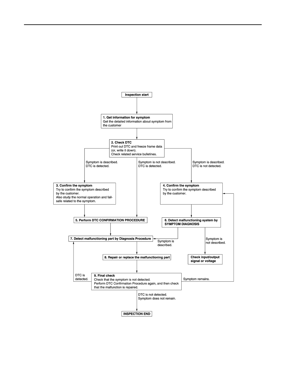
DIAGNOSIS AND REPAIR WORK FLOW
BASIC INSPECTION
DIAGNOSIS AND REPAIR WORK FLOW
Work Flow
INFOID:0000000010469917
OVERALL SEQUENCE
DETAILED FLOW
JMKIA8652GB