Qashqai J11. Exterior Lighting system - part 9


  Index      Nissan     Qashqai J11. Exterior Lighting system. Service and Repair Manual


Search            copyright infringement  


Content      ..     7      8      9      10     ..


Qashqai J11. Exterior Lighting system - part 9


STOP LAMP CIRCUIT

EXL-129

< DTC/CIRCUIT DIAGNOSIS >

[LED HEADLAMP]

C

D

E

F

G

H

I

J

K

M

A

B

EXL

N

O

P

2.

Connect BCM connector.

3.

Turn ignition switch ON.

4.

Check voltage between stop lamp switch harness connector and ground.

Is the inspection result normal?

YES

>> GO TO 5.

NO

>> Repair or replace harness.

5.

CHECK STOP LAMP SWITCH SIGNAL CIRCUIT (OPEN)

1.

Turn ignition switch OFF.

2.

Disconnect BCM connector.

3.

Check continuity between BCM harness connector and stop lamp switch harness connector.

Is the inspection result normal?

YES

>> GO TO 6.

NO

>> Repair or replace harness.

6.

CHECK STOP LAMP SWITCH

Check stop lamp switch. Refer to 

EXL-131, "Component Inspection"

.

Is the inspection result normal?

YES

>> Replace BCM. Refer to 

BCS-132, "Removal and Installation"

.

NO

>> Replace stop lamp switch. Refer to 

BR-17, "Exploded View"

 (LHD models) or 

BR-61, "Exploded

View"

 (RHD models).

7.

CHECK STOP LAMP / HIGH-MOUNTED STOP LAMP OUTPUT VOLTAGE

With CONSULT

1.

Disconnect stop lamp / tail lamp (body side) connectors.

2.

Turn ignition switch ON.

3.

Select “HEAD LAMP” of “BCM” using CONSULT.

4.

Select “STOP LAMP 1”, “STOP LAMP 2” or “STOP LAMP 3” in “Active Test” mode.

5.

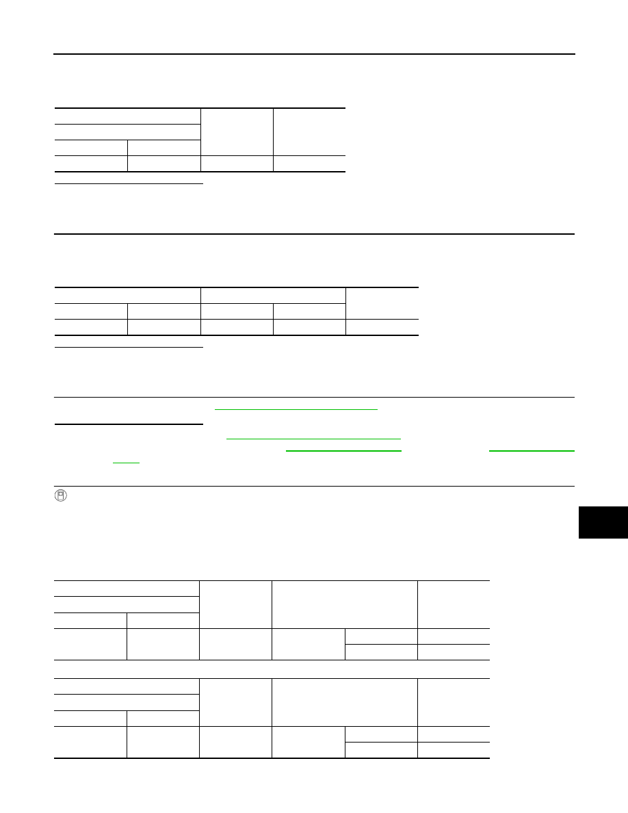
With operating the test items, check voltage between BCM harness connector and ground.

Stop lamp RH

Stop lamp LH

+

-

Voltage

Stop lamp switch

Connector

Terminal

E50

1

Ground

9 – 16 V

BCM

Stop lamp switch

Continuity

Connector

Terminal

Connector

Terminal

E60

157

E50

2

Existed

+

-

Test  item

Voltage

(Approx.)

BCM

Connector

Terminal

B3

134

Ground

STOP LAMP 1

On

9 – 16 V

Off

0 V

+

-

Test  item

Voltage

(Approx.)

BCM

Connector

Terminal

B3

129

Ground

STOP LAMP 2

On

9 – 16 V

Off

0 V

EXL-130

< DTC/CIRCUIT DIAGNOSIS >

[LED HEADLAMP]

STOP LAMP CIRCUIT

High-mounted stop lamp

Is the inspection result normal?

YES

>> GO TO 9.

NO

>> GO TO 8.

8.

CHECK STOP LAMP / HIGH-MOUNTED STOP LAMP POWER SUPPLY CIRCUIT (SHORT)

1.

Turn ignition switch OFF.

2.

Disconnect BCM connector.

3.

Check continuity between BCM harness connector and ground.

Stop lamp

High-mounted stop lamp

Is the inspection result normal?

YES

>> Replace BCM. Refer to 

BCS-132, "Removal and Installation"

.

NO

>> Repair or replace harness.

9.

CHECK STOP LAMP / HIGH-MOUNTED STOP LAMP POWER SUPPLY CIRCUIT (OPEN)

1.

Turn ignition switch OFF.

2.

Disconnect BCM connector.

3.

Check continuity between BCM harness connector and each stop lamp harness connector.

Stop lamp

High-mounted stop lamp

Is the inspection result normal?

YES

>> GO TO 10.

NO

>> Repair or replace harness.

10.

CHECK STOP LAMP / HIGH-MOUNTED STOP LAMP GROUND CIRCUIT

Check continuity between each stop lamp harness connector and ground.

+

-

Test item

Voltage

(Approx.)

BCM

Connector

Terminal

B4

39

Ground

STOP LAMP 3

On

9 – 16 V

Off

0 V

BCM

Continuity

Connector

Terminal

RH

B3

134

Ground

Not existed

LH

129

BCM

Continuity

Connector

Terminal

B4

39

Ground

Not existed

BCM

Stop lamp / tail lamp

Continuity

Connector

Terminal

Connector

Terminal

 RH

B3

134

B79

1

Existed

 LH

129

B22

BCM

High-mounted stop lamp

Continuity

Connector

Terminal

Connector

Terminal

B4

39

B17

2

Existed

STOP LAMP CIRCUIT

EXL-131

< DTC/CIRCUIT DIAGNOSIS >

[LED HEADLAMP]

C

D

E

F

G

H

I

J

K

M

A

B

EXL

N

O

P

Stop lamp

High-mounted stop lamp

Is the inspection result normal?

YES-1 >> Stop lamp: Replace the corresponding rear combination lamp. Refer to 

EXL-174, "Removal and

Installation"

.

YES-2 >> High-mounted stop lamp: Replace high-mounted stop lamp. Refer to 

EXL-177, "Removal and

Installation"

.

NO

>> Repair or replace harness.

Component Inspection

INFOID:0000000010338819

1.

CHECK STOP LAMP SWITCH-1

1.

Turn ignition switch OFF.

2.

Disconnect stop lamp switch connector.

3.

Check continuity of stop lamp switch terminals.

Is the inspection result normal?

YES

>> INSPECTION END

NO

>> GO TO 2.

2.

CHECK STOP LAMP SWITCH-2

1.

Adjust stop lamp switch installation. Refer to 

BR-8, "Inspection and Adjustment"

 (LHD models) or 

BR-52,

"Inspection and Adjustment"

 (RHD models).

2.

Check continuity of stop lamp switch terminals.

Is the inspection result normal?

YES

>> INSPECTION END

NO

>> Replace stop lamp switch. Refer to 

BR-17, "Exploded View"

 (LHD models) or 

BR-61, "Exploded

View"

 (RHD models).

Stop lamp / tail lamp

Continuity

Connector

Terminal

 RH

B79

2

Ground

Existed

 LH

B22

High-mounted stop lamp

Continuity

Connector

Terminal

B17

3

Ground

Existed

Stop lamp switch

Condition

Continuity

Terminal

1

2

Brake pedal

Depressed

Existed

Fully released

Not existed

Stop lamp switch

Condition

Continuity

Terminal

1

2

Brake pedal

Depressed

Existed

Fully released

Not existed

EXL-132

< DTC/CIRCUIT DIAGNOSIS >

[LED HEADLAMP]

FRONT FOG LAMP CIRCUIT

FRONT FOG LAMP CIRCUIT

Component Function Check

INFOID:0000000010338823

1.

CHECK FRONT FOG LAMP OPERATION

With CONSULT

1.

Select “FRONT FOG LAMP” in “Active Test” mode of “IPDM E/R” using CONSULT.

2.

With operating the test items, check that the front fog lamp is turned ON.

Is the inspection result normal?

YES

>> Front fog lamp circuit is normal.

NO

>> Refer to 

EXL-132, "Diagnosis Procedure"

.

Diagnosis Procedure

INFOID:0000000010338824

1.

CHECK FRONT FOG LAMP OUTPUT VOLTAGE

With CONSULT

1.

Turn ignition switch OFF.

2.

Disconnect front fog lamp connector.

3.

Turn ignition switch ON.

4.

Select “FRONT FOG LAMP” in “Active Test” mode of “IPDM E/R” using CONSULT.

5.

With operating the test items, check voltage between IPDM E/R harness connector and ground.

Is the inspection result normal?

YES

>> GO TO 2.

NO

>> Replace IPDM E/R. Refer to 

PCS-67, "Removal and Installation"

.

2.

CHECK FRONT FOG LAMP POWER SUPPLY CIRCUIT

1.

Turn ignition switch OFF.

2.

Disconnect IPDM E/R connector.

3.

Check continuity between IPDM E/R harness connector and front fog lamp harness connector.

Is the inspection result normal?

YES

>> GO TO 3.

NO

>> Repair or replace harness.

3.

CHECK FRONT FOG LAMP GROUND CIRCUIT

Check continuity between front fog lamp harness connector and ground.

On

: Front fog lamp ON

Off

: Front fog lamp OFF

+

-

Test item

Voltage

IPDM E/R

Connector

Terminal

RH

E101

49

Ground

FRONT FOG 
LAMP

On

9 – 16 V

Off

0 – 1 V

LH

E102

59

On

9 – 16 V

Off

0 – 1 V

IPDM E/R

Front fog lamp

Continuity

Connector

Terminal

Connector

Terminal

RH

E101

49

E95

1

Existed

LH

E102

59

E94

FRONT FOG LAMP CIRCUIT

EXL-133

< DTC/CIRCUIT DIAGNOSIS >

[LED HEADLAMP]

C

D

E

F

G

H

I

J

K

M

A

B

EXL

N

O

P

Is the inspection result normal?

YES

>> Replace the corresponding front fog lamp bulb. Refer to 

EXL-164, "Replacement"

.

NO

>> Repair or replace harness.

Front fog lamp

Continuity

Connector

Terminal

RH

E95

2

Ground

Existed

LH

E94

EXL-134

< DTC/CIRCUIT DIAGNOSIS >

[LED HEADLAMP]

REAR FOG LAMP CIRCUIT

REAR FOG LAMP CIRCUIT

Component Function Check

INFOID:0000000010338825

1.

CHECK REAR FOG LAMP OPERATION

With CONSULT

1.

Select “HEAD LAMP” of “BCM” using CONSULT.

2.

Select “RR FOG LAMP” in “Active Test” mode.

3.

With operating the test items, check that the rear fog lamp is turned ON.

Is the inspection result normal?

YES

>> Rear fog lamp circuit is normal.

NO

>> Refer to 

EXL-134, "Diagnosis Procedure"

.

Diagnosis Procedure

INFOID:0000000010338826

1.

CHECK REAR FOG LAMP OUTPUT VOLTAGE

With CONSULT

1.

Turn ignition switch OFF.

2.

Disconnect rear fog lamp connector. 

3.

Turn ignition switch ON.

4.

Select “HEAD LAMP” of “BCM” using CONSULT.

5.

Select “RR FOG LAMP” in “Active Test” mode.

6.

With operating the test items, check voltage between rear fog lamp harness connector and ground.

LHD models

RHD models

Is the inspection result normal?

YES

>> GO TO 4.

NO

>> GO TO 2.

2.

CHECK REAR FOG LAMP POWER SUPPLY CIRCUIT (OPEN)

1.

Turn ignition switch OFF.

2.

Disconnect BCM connector. 

3.

Check continuity between BCM harness connector and rear fog lamp harness connector. 

LHD models

On

: Rear fog lamp ON

Off

: Rear fog lamp OFF

+

-

Test item

Voltage

Rear fog lamp

Connector

Terminal

B24

1

Ground

RR FOG LAMP

On

9 – 16 V

Off

0 V

+

-

Test item

Voltage

Rear fog lamp

Connector

Terminal

D83

1

Ground

RR FOG LAMP

On

9 – 16 V

Off

0 V

BCM

Rear fog lamp

Continuity

Connector

Terminal

Connector

Terminal

B3

122

B24

1

Existed

REAR FOG LAMP CIRCUIT

EXL-135

< DTC/CIRCUIT DIAGNOSIS >

[LED HEADLAMP]

C

D

E

F

G

H

I

J

K

M

A

B

EXL

N

O

P

RHD models

Is the inspection result normal?

YES

>> GO TO 3.

NO

>> Repair or replace harness.

3.

CHECK REAR FOG LAMP POWER SUPPLY CIRCUIT (SHORT)

Check continuity between BCM harness connector and ground.

Is the inspection result normal?

YES

>> Replace BCM. Refer to 

BCS-132, "Removal and Installation"

.

NO

>> Repair or replace harness.

4.

CHECK REAR FOG LAMP GROUND CIRCUIT

1.

Turn ignition switch OFF.

2.

Check continuity between rear fog lamp harness connector and ground. 

LHD models

LHD models

Is the inspection result normal?

YES

>> GO TO 5.

NO

>> Repair or replace harness.

5.

CHECK REAR FOG LAMP BULB

Check rear fog lamp bulb.

Is the inspection result normal?

YES

>> Check rear fog lamp bulb socket. Repair or replace if necessary.

NO

>> Replace rear fog lamp bulb. Refer to 

EXL-175, "Replacement"

.

BCM

Rear fog lamp

Continuity

Connector

Terminal

Connector

Terminal

B3

122

D83

1

Existed

BCM

Continuity

Connector

Terminal

B3

122

Ground

Not existed

Rear fog lamp

Continuity

Connector

Terminal

B24

2

Ground

Existed

Rear fog lamp

Continuity

Connector

Terminal

D83

2

Ground

Existed

EXL-136

< DTC/CIRCUIT DIAGNOSIS >

[LED HEADLAMP]

TURN SIGNAL LAMP CIRCUIT

TURN SIGNAL LAMP CIRCUIT

Component Function Check

INFOID:0000000010338828

1.

CHECK TURN SIGNAL LAMP OPERATION

1.

Turn ignition switch ON.

2.

With operating the turn signal switch, check that the turn signal lamp is blinks.

Is the inspection result normal?

YES

>> Turn signal lamp circuit is normal.

NO

>> Refer to 

EXL-136, "Diagnosis Procedure"

.

Diagnosis Procedure

INFOID:0000000010338829

1.

CHECK SYMPTOM

Check symptom (A or B)

Which symptom is detected?

A

>> GO  TO  2.

B

>> GO  TO  4.

2.

CHECK FUSE

1.

Turn ignition switch OFF.

2.

Check that the following fuse is not fusing.

Is the inspection result normal?

YES

>> GO TO 3.

NO

>> Replace the blown fuse after repairing the affected circuit if a fuse is blown.

3.

CHECK BCM POWER SUPPLY (TURN SIGNAL LAMP)

1.

Disconnect BCM connector.

2.

Check voltage between BCM harness connector and ground.

Is the inspection result normal?

YES

>> Replace BCM. Refer to 

BCS-132, "Removal and Installation"

.

NO

>> Repair or replace harness.

4.

CHECK TURN SIGNAL LAMP OUTPUT VOLTAGE

1.

Turn ignition switch OFF.

2.

Disconnect the following connectors.

-

Front combination lamp

Right

: Turn signal lamps RH blink

Left

: Turn signal lamps LH blink

Center

: Turn signal lamps OFF

Symptom

A

All of turn signal lamp are not blinks

B

Applicable side performs high flasher activation

Unit

Location

Fuse No.

Capacity

BCM

Fuse block (J/B)

#33

10 A

+

-

Voltage

BCM

Connector

Terminal

M68

144

Ground

9 – 16 V

TURN SIGNAL LAMP CIRCUIT

EXL-137

< DTC/CIRCUIT DIAGNOSIS >

[LED HEADLAMP]

C

D

E

F

G

H

I

J

K

M

A

B

EXL

N

O

P

-

Door mirror

-

Rear turn signal lamp

3.

Turn ignition switch ON.

4.

With operating the turn signal switch, check voltage between BCM harness connector and ground.

Front turn signal lamp

Side turn signal lamp

+

-

Test item

Voltage

(Approx.)

BCM

Connector

Terminal

RH

E60

168

Ground

Turn signal 
switch

Right

Center

0 V

LH

167

Left

Center

0 V

+

-

Test item

Voltage

(Approx.)

BCM

Connector

Terminal

RH

M70

43

Ground

Turn signal 
switch

Right

Center

0 V

LH

42

Left

Center

0 V

PKID0926E

PKID0926E

PKID0926E

PKID0926E

EXL-138

< DTC/CIRCUIT DIAGNOSIS >

[LED HEADLAMP]

TURN SIGNAL LAMP CIRCUIT

Rear turn signal lamp

Is the inspection result normal?

YES

>> GO TO 6.

NO

>> GO TO 5.

5.

CHECK TURN SIGNAL LAMP POWER SUPPLY CIRCUIT (SHORT)

1.

Turn ignition switch OFF.

2.

Disconnect BCM connector.

3.

Check continuity between BCM harness connector and ground.

Front turn signal lamp

Side turn signal lamp

Rear turn signal lamp

Is the inspection result normal?

YES

>> Replace BCM. Refer to 

BCS-132, "Removal and Installation"

.

NO

>> Repair or replace harness.

6.

CHECK TURN SIGNAL LAMP POWER SUPPLY CIRCUIT (OPEN)

1.

Turn ignition switch OFF.

2.

Disconnect BCM connector.

+

-

Test  item

Voltage

(Approx.)

BCM

Connector

Terminal

RH

B3

136

Ground

Turn signal 
switch

Right

Center

0 V

LH

133

Left

Center

0 V

PKID0926E

PKID0926E

BCM

Continuity

Connector

Terminal

RH

E60

168

Ground

Not existed

LH

167

BCM

Continuity

Connector

Terminal

RH

M70

43

Ground

Not existed

LH

42

BCM

Continuity

Connector

Terminal

RH

B3

136

Ground

Not existed

LH

133

TURN SIGNAL LAMP CIRCUIT

EXL-139

< DTC/CIRCUIT DIAGNOSIS >

[LED HEADLAMP]

C

D

E

F

G

H

I

J

K

M

A

B

EXL

N

O

P

3.

Check continuity between BCM harness connector and each turn signal lamp harness connector.

Front turn signal lamp

Side turn signal lamp (LHD models)

Side turn signal lamp (RHD models)

Rear turn signal lamp

Is the inspection result normal?

YES

>> GO TO 7.

NO

>> Repair or replace harness.

7.

CHECK TURN SIGNAL LAMP GROUND CIRCUIT

Check continuity between each turn signal lamp harness connector and ground.

Front turn signal lamp

Side turn signal lamp (LHD models)

Side turn signal lamp (RHD models)

BCM

Front combination lamp

Continuity

Connector

Terminal

Connector

Terminal

 RH

E60

168

E93

8

Existed

 LH

167

E91

BCM

Door mirror

Continuity

Connector

Terminal

Connector

Terminal

 RH

M70

43

D27

13

Existed

 LH

42

D3

BCM

Door mirror

Continuity

Connector

Terminal

Connector

Terminal

 RH

M70

43

D40

13

Existed

 LH

42

D16

BCM

Rear turn signal lamp

Continuity

Connector

Terminal

Connector

Terminal

 RH

B3

136

B80

1

Existed

 LH

133

B23

Front combination lamp

Continuity

Connector

Terminal

 RH

E93

6

Ground

Existed

 LH

E91

Door mirror

Continuity

Connector

Terminal

 RH

D27

14

Ground

Existed

 LH

D3

Door mirror

Continuity

Connector

Terminal

 RH

D40

14

Ground

Existed

 LH

D16

EXL-140

< DTC/CIRCUIT DIAGNOSIS >

[LED HEADLAMP]

TURN SIGNAL LAMP CIRCUIT

Rear turn signal lamp

Is the inspection result normal?

YES-1 >> Front turn signal lamp or rear turn signal lamp: GO TO 8.
YES-2 >> Side turn signal lamp: Replace side turn signal lamp. Refer to 

EXL-166, "Removal and Installa-

tion"

.

NO

>> Repair or replace harness.

8.

CHECK TURN SIGNAL LAMP BULB

Check the applicable turn signal lamp bulb.

Is the inspection result normal?

YES

>> Check the corresponding turn signal lamp bulb socket. Repair or replace if necessary.

NO

>> Replace the corresponding turn signal lamp bulb. Refer to 

EXL-162, "Replacement"

 (front turn

signal lamp) or 

EXL-175, "Replacement"

 (rear turn signal lamp).

Rear turn signal lamp

Continuity

Connector

Terminal

 RH

B80

2

Ground

Existed

 LH

B23

LIGHT & RAIN SENSOR

EXL-141

< DTC/CIRCUIT DIAGNOSIS >

[LED HEADLAMP]

C

D

E

F

G

H

I

J

K

M

A

B

EXL

N

O

P

LIGHT & RAIN SENSOR

Component Function Check

INFOID:0000000010452494

1.

CHECK LIGHT & RAIN SENSOR

1.

Clean light & rain sensor detection area of windshield fully.

2.

Turn ignition switch ON.

3.

Turn lighting switch AUTO.

4.

With the light & rain sensor illuminating, check the auto light function. 

Is the inspection result normal?

YES

>> Light & rain sensor is normal.

NO

>> Refer to 

EXL-141, "Diagnosis Procedure"

.

Diagnosis Procedure

INFOID:0000000010452495

1.

CHECK LIGHT & RAIN SENSOR POWER SUPPLY

1.

Turn ignition switch OFF

2.

Disconnect light & rain sensor connector.

3.

Turn ignition switch ON.

4.

Check voltage between light & rain sensor harness connector and ground.

Is the inspection result normal?

YES

>> GO TO 3.

NO

>> GO TO 2.

2.

CHECK LIGHT & RAIN SENSOR POWER SUPPLY CIRCUIT

1.

Turn ignition switch OFF.

2.

Remove room lamp relay.

3.

Check continuity between room lamp relay harness connector and light & rain sensor harness connector.

Is the inspection result normal?

YES

>> Perform the interior room lamp power supply circuit diagnosis. Refer to 

INL-55, "Diagnosis Proce-

dure"

.

NO

>> Repair or replace harness.

3.

CHECK LIGHT & RAIN SENSOR GROUND CIRCUIT

Check continuity between light & rain sensor harness connector and ground.

Condition

Auto light function

Light & rain sensor

When illuminating

Not operating

When shutting off light

Operating

+

-

Voltage

Light & rain sensor

Connector

Terminal

R5

1

Ground Battery 

voltage

Room lamp relay

Light & rain sensor

Continuity

Connector

Terminal

Connector

Terminal

M80

7

R5

1

Existed

Light & rain sensor

Continuity

Connector

Terminal

R5

3

Ground

Existed

EXL-142

< DTC/CIRCUIT DIAGNOSIS >

[LED HEADLAMP]

LIGHT & RAIN SENSOR

Is the inspection result normal?

YES

>> GO TO 4.

NO

>> Repair or replace harness.

4.

CHECK LIGHT & RAIN SENSOR SIGNAL

1.

Connect light & rain sensor connector.

2.

Turn ignition switch ON.

3.

Check voltage between BCM harness connector and ground.

Is the inspection result normal?

YES

>> Replace light & rain sensor. Refer to 

EXL-171, "Removal and Installation"

.

NO

>> GO TO 5.

5.

CHECK LIGHT & RAIN SENSOR SIGNAL CIRCUIT (OPEN)

1.

Turn ignition switch OFF.

2.

Disconnect BCM connector and light & rain sensor connector.

3.

Check continuity between BCM harness connector and light & rain sensor harness connector.

Is the inspection result normal?

YES

>> GO TO 6.

NO

>> Repair or replace harness.

6.

CHECK LIGHT & RAIN SENSOR SIGNAL CIRCUIT (SHORT)

Check continuity between BCM harness connector and ground.

Is the inspection result normal?

YES

>> Replace BCM. Refer to 

BCS-132, "Removal and Installation"

.

NO

>> Repair or replace harness.

+

-

Condition

Voltage

(Approx.)

BCM

Connector

Terminal

M70

47

Ground 

Ignition switch 
ON

8.7V

JPMIA0156GB

BCM

Light & rain sensor

Continuity

Connector

Terminal

Connector

Terminal

M70

47

R5

2

Existed

BCM

Continuity

Connector

Terminal

M70

47

Ground

Not existed

HAZARD SWITCH

EXL-143

< DTC/CIRCUIT DIAGNOSIS >

[LED HEADLAMP]

C

D

E

F

G

H

I

J

K

M

A

B

EXL

N

O

P

HAZARD SWITCH

Component Function Check

INFOID:0000000010338832

1.

CHECK HAZARD SWITCH SIGNAL

With CONSULT

1.

Turn ignition switch ON.

2.

Select “FLASHER” of “BCM” using CONSULT.

3.

Select “HAZARD SW” in “Data Monitor” mode.

4.

With operating the hazard switch, check the monitor status.

Is the inspection result normal?

YES

>> Hazard switch circuit is normal.

NO

>> Refer to 

EXL-143, "Diagnosis Procedure"

.

Diagnosis Procedure

INFOID:0000000010338833

1.

CHECK HAZARD SWITCH SIGNAL

1.

Turn ignition switch OFF.

2.

Disconnect hazard switch connector.

3.

Check voltage between hazard switch connector and ground.

Is the inspection result normal?

YES

>> GO TO 4.

NO

>> GO TO 2.

2.

CHECK HAZARD SWITCH SIGNAL CIRCUIT (OPEN)

1.

Disconnect BCM connector.

2.

Check continuity between hazard switch harness connector and BCM harness connector.

Is the inspection result normal?

YES

>> GO TO 3.

NO

>> Repair or replace harness.

3.

CHECK HAZARD SWITCH SIGNAL CIRCUIT (SHORT)

Check continuity between hazard switch harness connector and ground.

Is the inspection result normal?

YES

>> Replace BCM. Refer to 

BCS-132, "Removal and Installation"

.

Monitor item

Condition

Monitor status

HAZARD SW

Hazard switch

ON

On

OFF

Off

+

-

Voltage

Hazard switch

Connector

Terminal

M39

2

Ground

9 – 16 V

Hazard switch

BCM

Continuity

Connector

Terminal

Connector

Terminal

M39

2

M70

51

Existed

Hazard switch

Continuity

Connector

Terminal

M39

2

Ground

Not existed

EXL-144

< DTC/CIRCUIT DIAGNOSIS >

[LED HEADLAMP]

HAZARD SWITCH

NO

>> Repair or replace harness.

4.

CHECK HAZARD SWITCH GROUND CIRCUIT

Check continuity between hazard switch harness connector and ground.

Is the inspection result normal?

YES

>> GO TO 5.

NO

>> Repair or replace harness.

5.

CHECK HAZARD SWITCH

Check hazard switch. Refer to 

EXL-144, "Component Inspection"

.

Is the inspection result normal?

YES

>> INSPECTION END

NO

>> Replace hazard switch. Refer to 

EXL-168, "Removal and Installation"

.

Component Inspection

INFOID:0000000010452497

1.

CHECK HAZARD SWITCH

1.

Turn ignition switch OFF.

2.

Disconnect hazard switch connector.

3.

Check continuity of hazard switch terminals.

Is the inspection result normal?

YES

>> INSPECTION END

NO

>> Replace hazard switch. Refer to 

EXL-168, "Removal and Installation"

.

Hazard switch

Continuity

Connector

Terminal

M39

1

Ground

Existed

Hazard switch

Condition

Continuity

Terminal

1

2

Hazard switch

ON

Existed

OFF

Not existed


Content      ..     7      8      9      10     ..