Qashqai J11. Exterior Lighting system - part 2


  Index      Nissan     Qashqai J11. Exterior Lighting system. Service and Repair Manual


Search            copyright infringement  


Content      ..      1      2      3      ..


Qashqai J11. Exterior Lighting system - part 2


SYSTEM

EXL-17

< SYSTEM DESCRIPTION >

[LED HEADLAMP]

C

D

E

F

G

H

I

J

K

M

A

B

EXL

N

O

P

SYSTEM

HEADLAMP SYSTEM

HEADLAMP SYSTEM : System Description

INFOID:0000000010338642
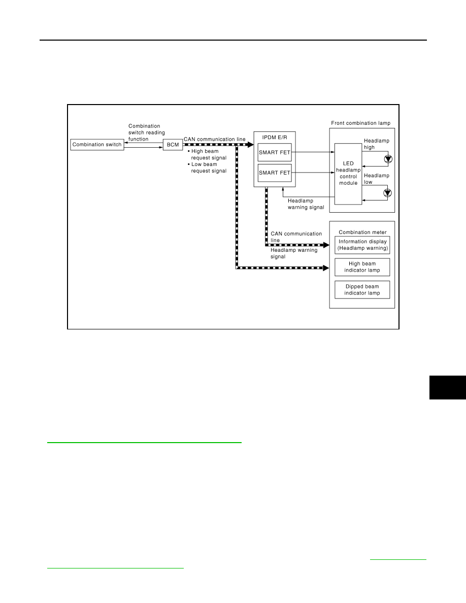
SYSTEM DIAGRAM

OUTLINE

Headlamp is controlled by combination switch reading function and headlamp control function of BCM, and
smart FET control function of IPDM E/R.

HEADLAMP (LO) OPERATION 

• BCM detects the combination switch condition with the combination switch reading function.
• BCM transmits the low beam request signal to IPDM E/R and the combination meter with CAN communica-

tion according to the headlamp (LO) ON condition.

Headlamp (LO) ON condition (When any of the following conditions are satisfied)

- Lighting switch 2ND
- Lighting switch AUTO (Only when the illumination judgment by auto light system is ON. For details, refer to

EXL-19, "AUTO LIGHT SYSTEM : System Description"

.)

- Lighting switch PASS
• IPDM E/R turns the integrated smart FET ON according to low beam request signal and supplies power sup-

ply to LED headlamp control module.

• LED headlamp control module turns the headlamp (LO) ON according to the power supply from IPDM E/R.
• Combination meter turns the dipped beam indicator lamp ON according to the low beam request signal.

HEADLAMP (HI) OPERATION

• BCM transmits the high beam request signal to IPDM E/R and the combination meter with CAN communica-

tion according to the headlamp (HI) ON condition. 

Headlamp (HI) ON condition (When any of the following conditions are satisfied)

- Lighting switch HI with the lighting switch 2ND
- Lighting switch HI with the lighting switch AUTO (Only when the illumination judgment by auto light system is

ON and the illumination judgment by high beam assist system is ON. For details, refer to 

EXL-19, "AUTO

LIGHT SYSTEM : System Description"

.)

- Lighting switch PASS

JMLIA5227GB

EXL-18

< SYSTEM DESCRIPTION >

[LED HEADLAMP]

SYSTEM

• IPDM E/R turns the integrated headlamp high smart FET ON according to high beam request signal and

supplies power supply to LED headlamp control module.

• LED headlamp control module turns the headlamp (HI) ON according to the power supply from IPDM E/R.
• Combination meter turns the high beam indicator lamp ON according to the high beam request signal. 

HEADLAMP WARNING OPERATION

• BCM transmits the low beam request signal to IPDM E/R with CAN communication when headlamp (LO) ON

judgment.

• When LED headlamp control module detects a malfunction of headlamp (LO) circuit, headlamp warning sig-

nal is output to IPDM E/R.

• When the IPDM E/R receives the low beam request signal and the headlamp warning signal is input, it trans-

mits the headlamp warning signal (CAN communication) to the combination meter.

• When the ignition switch is ON and the combination meter receives the headlamp warning signal, the combi-

nation meter displays the headlamp warning on the vehicle information display.
NOTE:
When the headlamp warning signal is received, the most likely cause is a malfunction of the following.
• Headlamp (LO) power supply/ground circuit
• Headlamp warning signal circuit
• Front combination lamp internal circuit
- LED (Headlamp low)
- LED headlamp control module
- Harness

FOLLOW ME HOME FUNCTION

When the driver is moving to the house entrance from the own vehicle, headlamp is kept still ON by the follow
me home function of BCM.
• When BCM detects the input of lighting switch PASS while all of the following conditions are satisfied, it

transmits the low beam request signal for a period of time to IPDM E/R and the combination meter through
CAN communication.

Follow me home ON condition (When all of the following conditions are satisfied)

- Ignition switch OFF
- Lighting switch OFF or AUTO
• IPDM E/R turns the integrated smart FET ON according to low beam request signal and supplies power sup-

ply to LED headlamp control module.

• LED headlamp control module turns the headlamp (LO) ON according to the power supply from IPDM E/R.
• Combination meter turns the dipped beam indicator lamp ON according to the low beam request signal.
• When in any of following conditions, follow me home function can be cancelled while follow me home func-

tion is operating.

Follow me home OFF condition (When any of the following conditions are satisfied)

- Ignition switch other than OFF
- Lighting switch other than OFF or AUTO
- Follow me home operating time is expired
NOTE:
• Flash-to-pass operation illumination time for 1 time can be extended to approximately 30 seconds during

operation of follow me home function.

• Flash-to-pass operation can be illuminated continuously for approximately 60 seconds (flash-to-pass opera-

tion, 2 times), approximately 90 seconds (flash-to-pass operation, 3 times), and a maximum of approxi-
mately 120 seconds (flash-to-pass operation, 4 times).

HEADLAMP SYSTEM : Fail-safe

INFOID:0000000010338644

FAIL-SAFE CONTROL BY DTC

IPDM E/R performs fail-safe control when any DTC are detected.

SYSTEM

EXL-19

< SYSTEM DESCRIPTION >

[LED HEADLAMP]

C

D

E

F

G

H

I

J

K

M

A

B

EXL

N

O

P

CAN COMMUNICATION CONTROL

When CAN communication with BCM is impossible, IPDM E/R performs fail-safe control. After CAN communi-
cation recovers normally, it also returns to normal control.

If No CAN Communication Is Available With BCM

AUTO LIGHT SYSTEM

AUTO LIGHT SYSTEM : System Description

INFOID:0000000010338645

SYSTEM DIAGRAM

OUTLINE

•  Auto light system is controlled by each function of BCM and IPDM E/R.

DTC

CONSULT display description

Fail-safe

B20CE

HL (HI) LH PWR SPLY CIRC

[CIRC 
SHORT TO 
GRND]

Shuts off the power supply to the headlamp (HI) LH power 
supply circuit until the headlamp (HI) ON conditions are 
no longer satisfied.

B20CF

HL (HI) RH PWR SPLY CIRC

[CIRC 
SHORT TO 
GRND]

Shuts off the power supply to the headlamp (HI) RH pow-
er supply circuit until the headlamp (HI) ON conditions are 
no longer satisfied.

B20D0

HL (LO) LH PWR SPLY CIRC

[CIRC 
SHORT TO 
GRND]

Shuts off the power supply to the headlamp (LO) LH pow-
er supply circuit until the headlamp (LO) ON conditions 
are no longer satisfied.

B20D1

HL (LO) RH PWR SPLY CIRC

[CIRC 
SHORT TO 
GRND]

Shuts off the power supply to the headlamp (LO) RH pow-
er supply circuit until the headlamp (LO) ON conditions 
are no longer satisfied.

B20E2

LED HEADLAMP RH

[CMPNENT 
INTERNAL 
MLFNCTN]

Transmits the headlamp warning signal (CAN communi-
cation) to the combination meter when the headlamp (LO) 
ON conditions are satisfied. (When the ignition switch 
turns ON, the headlamp warning is displayed on the infor-
mation display of the combination meter.)

B20E3

LED HEADLAMP LH

[CMPNENT 
INTERNAL 
MLFNCTN]

Transmits the headlamp warning signal (CAN communi-
cation) to the combination meter when the headlamp (LO) 
ON conditions are satisfied. (When the ignition switch 
turns ON, the headlamp warning is displayed on the infor-
mation display of the combination meter.)

Control part

Fail-safe operation

Headlamp

• Turns ON the headlamp (LO) when the ignition switch is turned ON.
• Turns OFF the headlamp (LO) when the ignition switch is turned OFF.
• Headlamp (HI): OFF

JMLIA5228GB

EXL-20

< SYSTEM DESCRIPTION >

[LED HEADLAMP]

SYSTEM

Control by BCM

- Combination switch reading function
- Auto light function
- Fog override function

Control by IPDM E/R

- Smart FET control function
• Auto light system has the auto light function and fog override function.
- Auto light function automatically turns ON/OFF the exterior lamps*, depending on the outside brightness.
- Fog override function turns ON the exterior lamps regardless of outside brightness, when front fog lamp

switch is turned from OFF to ON or rear fog lamp switch is turned from OFF to ON while ignition switch is in
ON position and lighting switch is in AUTO position.

*: Headlamp (LO/HI), front fog lamp, rear fog lamp, parking lamp, license plate lamp and tail lamp.
NOTE:
• Headlamp (HI) depend on the combination switch condition and the illumination judgment of high beam

assist system. For details, refer to 

EXL-21, "HIGH BEAM ASSIST SYSTEM : System Description"

.

• Front fog lamp depend on the front fog lamp switch condition (only when the fog override function setting is

OFF). (without rear fog lamp)

• Front fog lamp does not turn ON automatically, but automatically turns OFF (only when the fog override

function setting is OFF). (with rear fog lamp)

• Rear fog lamp does not turn ON automatically, but automatically turns OFF (only when the fog override func-

tion setting is OFF).

AUTO LIGHT FUNCTION

• BCM detects the combination switch condition with the combination switch reading function.
• BCM detects the engine condition by the engine status signal received from ECM via CAN communication.
• BCM receives exterior lamp ON/OFF requests from the light & rain sensor by light & rain sensor serial link.
• BCM judges the ON/OFF status of the exterior lamp according to ON/OFF requests from light & rain sensor

and the vehicle condition.

• BCM transmits each request signal to IPDM E/R via CAN communication according to ON/OFF condition by

the auto light function.

NOTE:
ON/OFF timing differs based on the sensitivity from the setting. The setting can be set by CONSULT. Refer to

EXL-33, "HEADLAMP : CONSULT Function (BCM - HEAD LAMP) (LED Headlamp)"

.

FOG OVERRIDE FUNCTION

When front fog lamp switch is turned from OFF to ON or rear fog lamp switch is turned from OFF to ON while
ignition switch is in ON position and lighting switch is in AUTO position, BCM turns ON exterior lamps* regard-
less of outside brightness.
*: Headlamp (LO/HI), front fog lamp, rear fog lamp, parking lamp, license plate lamp and tail lamp.
NOTE:
• Headlamp (HI) depend on the combination switch condition and the illumination judgment of high beam

assist system. For details, refer to 

EXL-21, "HIGH BEAM ASSIST SYSTEM : System Description"

.

• Front fog lamp and rear fog lamp does not turn ON automatically (depend on the each fog lamp switch oper-

ation).

• ON/OFF of fog override function can be changed using CONSULT. Refer to 

INL-15, "INT LAMP : CONSULT

Function (BCM - INT LAMP)"

.

HIGH BEAM ASSIST SYSTEM

SYSTEM

EXL-21

< SYSTEM DESCRIPTION >

[LED HEADLAMP]

C

D

E

F

G

H

I

J

K

M

A

B

EXL

N

O

P

HIGH BEAM ASSIST SYSTEM : System Description

INFOID:0000000010338647

SYSTEM DIAGRAM

OUTLINE

• High beam assist system is a system that can reduce the driver's switch operation load. The system auto-

matically switches the headlamp to the low beam mode when a vehicle ahead or an oncoming vehicle
appears, while driving the vehicle with the headlamps in high beam mode at night.

• When the high beam assist system operation permission conditions are satisfied, the high beam assist indi-

cator lamp in the combination meter turns ON and informs that the high beam assist is in operation.

• High beam assist system is controlled by each function of BCM, front camera unit and IPDM E/R.

Control by BCM

- Combination switch reading function
- Auto light function
- High beam assist control function
- Headlamp control function

Control by IPDM E/R

- Smart FET control function

Control by Front camera unit

- High beam assist control function

OPERATION DESCRIPTION

• BCM detects the combination switch condition with the combination switch reading function.
• BCM transmits the high beam assist indicator lamp signal to the combination meter via CAN communication

when the high beam assist system operation permission conditions are satisfied.

High beam assist system operation permission conditions

- Lighting switch HI with the lighting switch AUTO and ignition switch ON (Only when the illuminating judgment

by auto light function is ON. For details, refer to 

EXL-19, "AUTO LIGHT SYSTEM : System Description"

.)

• Combination meter turns the high beam assist indicator lamp ON according to the high beam assist indicator

lamp signal.

• Front camera unit detects the vehicle status and ambient status that are required for high beam assist con-

trol with the following signals.

- Vehicle speed signal (received from combination meter via CAN communication)
- Ambient light signal (input from ambient light sensor integrated in the front camera unit)
- Image sensor signal (input from image sensor integrated in the front camera unit)
• Front camera unit judges the current recommended beam according to the vehicle status and ambient con-

dition, and transmits the high beam assist request signal (headlamp HI operation / headlamp LO operation)
to BCM via CAN communication.

• BCM switches the headlamp LO operation / headlamp HI operation according to high beam assist request

signal while the high beam assist system operation permission conditions are satisfied. For headlamp oper-
ation, refer to 

EXL-17, "HEADLAMP SYSTEM : System Description"

.

RECOMMENDED BEAM JUDGMENT BY FRONT CAMERA UNIT

JMLIA5229GB

EXL-22

< SYSTEM DESCRIPTION >

[LED HEADLAMP]

SYSTEM

Headlamp HI Operation Request

Front camera unit requests the headlamp HI operation to BCM when all of following conditions are satisfied.
• Detects the vehicle speed is approx. 40 km/h or more.
• Recognizes the ambient condition is dark.
• Recognizes there is no oncoming vehicle or no vehicle ahead in front of the vehicle.

Headlamp LO Operation Request

Front camera unit requests the headlamp LO operation to BCM when either of following conditions is satisfied.
• Detects the vehicle speed is approx. 30 km/h or less.
• Recognizes the ambient condition is bright.
• Recognizes there is oncoming vehicle or vehicle ahead in front of the vehicle.

HIGH BEAM ASSIST SYSTEM : Fail-safe

INFOID:0000000010338649

FRONT CAMERA UNIT TEMPORARY OPERATION CANCELLATION

• Temporary disabled status at high temperature
- If the vehicle is parked in direct sunlight under high temperature conditions, the system may be deactivated

automatically. And the system malfunction in information display.

- When interior temperature is reduced, the system will resume operation automatically.
• When vehicle front identification is difficult
- When vehicle front identification is difficult due to soiling of windshield glass and strong light shining from the

front, operation may be canceled temporarily. At this time, a warning is displayed on the vehicle information
display in the combination meter.

- Normal operation recovers when conditions improve.

DAYTIME RUNNING LIGHT SYSTEM

DAYTIME RUNNING LIGHT SYSTEM : System Description

INFOID:0000000010338650

SYSTEM DIAGRAM

OUTLINE

Daytime running light is controlled by daytime running light control function and combination switch reading
function of BCM, and smart FET control function of IPDM E/R.

DAYTIME RUNNING LIGHT OPERATION 

• BCM detects the combination switch condition by the combination switch reading function.
• BCM detects vehicle condition depending on the engine status signal and Stop/Start status signal* (received

from ECM via CAN communication).

• BCM transmits the daytime running light request signal to IPDM E/R via CAN communication according to

the daytime running light ON condition.

Daytime running light ON condition

- Engine running and any following conditions are satisfied.
• Lighting switch OFF
• Lighting switch AUTO (Only when the illumination judgment by auto light system is OFF. For details, refer to

EXL-19, "AUTO LIGHT SYSTEM : System Description"

.)

JMLIA5230GB

SYSTEM

EXL-23

< SYSTEM DESCRIPTION >

[LED HEADLAMP]

C

D

E

F

G

H

I

J

K

M

A

B

EXL

N

O

P

• IPDM E/R turns the integrated smart FET ON, and turns the daytime running light ON according to the day-

time running light request signal.

NOTE:
When the engine is stopped by the Stop/Start system, the operation of daytime running light system is not can-
celed.*
*: With Stop/Start system

DAYTIME RUNNING LIGHT SYSTEM : Fail-safe

INFOID:0000000010338652

FAIL-SAFE CONTROL BY DTC

IPDM E/R performs fail-safe control when any DTC are detected.

CAN COMMUNICATION CONTROL

When CAN communication with BCM is impossible, IPDM E/R performs fail-safe control. After CAN communi-
cation recovers normally, it also returns to normal control.

If No CAN Communication Is Available With BCM

HEADLAMP AIMING CONTROL SYSTEM (AUTO)

HEADLAMP AIMING CONTROL SYSTEM (AUTO) : System Description

INFOID:0000000010338656

SYSTEM DIAGRAM

OUTLINE

• Headlamp aiming control system is controlled by IPDM E/R.
• IPDM E/R controls the headlamp light axis height appropriately depending on the vehicle rear height.
• IPDM E/R detects the vehicle condition necessary for the headlamp aiming motor control with the following

signals.

- Height sensor signal (inputted from height sensor)
- Low beam request signal (received from BCM via CAN communication)
- Vehicle speed signal (received from combination meter via CAN communication)

HEADLAMP AUTO AIMING OPERATION

DTC

CONSULT display description

Fail-safe

B1231

DTRL RH PWR SPLY CIRC

[CIRC 
SHORT TO 
GRND]

Shuts off the power supply to the daytime running light RH 
power supply circuit until the daytime running light ON 
conditions are no longer satisfied.

B20CB

DTRL LH PWR SPLY CIRC

[CIRC 
SHORT TO 
GRND]

Shuts off the power supply to the daytime running light LH 
power supply circuit until the daytime running light ON 
conditions are no longer satisfied.

Control part

Fail-safe operation

Daytime running light

Daytime running light: OFF

JMLIA5231GB

EXL-24

< SYSTEM DESCRIPTION >

[LED HEADLAMP]

SYSTEM

• IPDM E/R calculates vehicle pitch angle from height sensor signal and determines the necessary correction

to compensate the deviation from standard light axis position.

• IPDM E/R outputs aiming motor drive signal when operating conditions are satisfied.

Operating condition (when all of the following conditions are satisfied)

- Ignition switch ON
- Headlamp (LO) ON
• IPDM E/R changes the aiming motor drive signal when any of the correcting condition is detected. Output is

maintained if other condition is detected.

Correcting condition (when any of the following conditions are satisfied)

- Ignition switch ON
- Headlamp (LO) is turned ON.
- Vehicle posture becomes stable after the vehicle posture change is detected with the headlamp (LO) ON

and the vehicle stopped.

- Vehicle speed is maintained with the headlamp (LO) ON and the vehicle driven.
NOTE:
Adjusted axis position may differ from the preset position although the headlamp auto aiming activates prop-
erly when the suspension is replaced or worn.

HEADLAMP AIMING CONTROL SYSTEM (AUTO) : Fail-safe

INFOID:0000000010338658

FAIL-SAFE CONTROL BY DTC

IPDM E/R performs fail-safe control when any DTC are detected.

DTC

CONSULT display description

Fail-safe

B1C00

HEIGHT SENSOR PWR SPLY CIRC

[CIRC 
SHORT TO 
GRND]

Right and left headlamp aiming motors stop at the posi-
tion when DTC is detected.

[CIRC 
SHORT TO 
BATTERY]

B1C02

RR HEIGHT SENSOR SIGNAL

[CIRC 
SHORT TO 
BATTERY]

Right and left headlamp aiming motors stop at the posi-
tion when DTC is detected.

[CIRC 
SHORT TO 
GROUND 
OR OPEN]

[CIRC 
VOLTAGE 
OUT OF 
RANGE]

B1C07

AIMING MOTOR DRIVE SIGNAL

[CIRC 
SHORT TO 
GRND]

Right and left headlamp aiming motors stop at the posi-
tion when DTC is detected.

[CIRC 
SHORT TO 
BATTERY]

[SIGNAL 
COMPARE 
FAILURE]

B1C12

RR HEIGHT SENSOR SIGNAL

[SIG 
PRTCTN 
CLCLTN IN-
CRCT]

Right and left headlamp aiming motors stop at the posi-
tion when DTC is detected.

SYSTEM

EXL-25

< SYSTEM DESCRIPTION >

[LED HEADLAMP]

C

D

E

F

G

H

I

J

K

M

A

B

EXL

N

O

P

TURN SIGNAL AND HAZARD WARNING LAMP SYSTEM

TURN SIGNAL AND HAZARD WARNING LAMP SYSTEM : System Description

INFOID:0000000010338659

SYSTEM DIAGRAM

OUTLINE

Turn signal lamp and hazard warning lamp is controlled by combination switch reading function and the flasher
control function of BCM.

TURN SIGNAL LAMP OPERATION

• BCM detects the combination switch condition by the combination switch reading function.
• BCM supplies voltage to the right (left) turn signal lamp circuit when the ignition switch is ON and the turn

signal switch is in the right (left) position. BCM blinks the turn signal lamp.

HAZARD WARNING LAMP OPERATION

BCM supplies voltage to both turn signal lamp circuits when the hazard switch is ON. BCM blinks the hazard
warning lamp.

TURN SIGNAL INDICATOR LAMP AND TURN SIGNAL OPERATION

• BCM transmits the turn indicator signal to the combination meter using CAN communication while the turn

signal lamp and the hazard warning lamp are operating.

• Combination meter outputs the turn signal sound with the integrated buzzer while blinking the turn signal

indicator lamp according to the turn indicator signal.

3-TIME FLASHER FUNCTION

• By a short touch of the turn signal lever, BCM blinks the turn signal lamps 3 times in the selected direction.
• Cancels the operation when short touch of the turn signal lever in the reverse direction during the 3-time

flasher function operation.

NOTE:
ON/OFF of 3-time flasher function can be changed using CONSULT. Refer to 

EXL-35, "FLASHER : CONSULT

Function (BCM - FLASHER) (LED Headlamp)"

.

HIGH FLASHER OPERATION

• BCM detects the turn signal lamp circuit status from the current value.
• BCM increases the turn signal lamp blinking speed if the bulb or harness open is detected with the turn sig-

nal lamp operating.
NOTE:

B20DB

HEIGHT SENS INITIALIZE NOT DONE

[MISSING 
CALIBRA-
TION]

Right and left headlamp aiming motors fix at the initial 
aiming position.

[NOT CON-
FIURED]

DTC

CONSULT display description

Fail-safe

JMLIA5232GB

EXL-26

< SYSTEM DESCRIPTION >

[LED HEADLAMP]

SYSTEM

The blinking speed is normal while operating the hazard warning lamp.

AUTO HAZARD FUNCTION

• Air bag diagnosis sensor unit transmits car crash information signal to BCM via CAN communication, when

air bag diagnosis sensor unit detects strong impact to the vehicle body while ignition switch is ON.

• When car crash information signal received from air bag diagnosis sensor unit is detected, BCM supplies

voltage to each turn signal lamp system and hazard lamp blinks.

PARKING, LICENSE PLATE AND TAIL LAMP SYSTEM

PARKING, LICENSE PLATE AND TAIL LAMP SYSTEM : System Description

INFOID:0000000010338661

SYSTEM DIAGRAM

OUTLINE

Parking, license plate and tail lamps are controlled by combination switch reading function and parking,
license plate and tail lamps control function of BCM, and smart FET control function of IPDM E/R.

PARKING, LICENSE PLATE AND TAIL LAMPS OPERATION 

• BCM detects the combination switch condition by the combination switch reading function.
• BCM transmits the position light request signal to IPDM E/R and the combination meter via CAN communi-

cation according to the parking, license plate and tail lamps ON condition.

Parking, license plate and tail lamps ON condition (when any of the following conditions are satisfied)

- Lighting switch 1ST
- Lighting switch 2ND
- Lighting switch AUTO (Only when the illumination judgment by auto light system is ON. For details, refer to

EXL-19, "AUTO LIGHT SYSTEM : System Description"

.)

• IPDM E/R turns the integrated smart FET ON and turns the parking, license plate and tail lamps ON accord-

ing to the position light request signal.

• Combination meter turns the position lamp indicator lamp ON according to the position light request signal.
NOTE:
Parking lamp and daytime running light use a common light source. When the parking, license plate and tail
lamps are turned ON while daytime running light is ON, the parking lamp/daytime running light is dimmed.

FOLLOW ME HOME FUNCTION

When the driver is moving to the house entrance from the own vehicle, parking, license plate and tail lamps
are kept still ON by the follow me home function of BCM.
• When BCM detects the input of lighting switch PASS while all of the following conditions are satisfied, it

transmits the position light request signal for a period of time to IPDM E/R and the combination meter
through CAN communication.

Follow me home ON condition (When all of the following conditions are satisfied)

- Ignition switch OFF

JMLIA5233GB

SYSTEM

EXL-27

< SYSTEM DESCRIPTION >

[LED HEADLAMP]

C

D

E

F

G

H

I

J

K

M

A

B

EXL

N

O

P

- Lighting switch OFF or AUTO
• IPDM E/R turns the integrated smart FET ON and turns the parking, license plate and tail lamps ON accord-

ing to the position light request signal.

• Combination meter turns the position lamp indicator lamp ON according to the position light request signal.
• When in any of following conditions, follow me home function can be cancelled while follow me home func-

tion is operating.

Follow me home OFF condition (When any of the following conditions are satisfied)

- Ignition switch other than OFF
- Lighting switch other than OFF or AUTO
- Follow me home operating time is expired
NOTE:
• Flash-to-pass operation illumination time for 1 time can be extended to approximately 30 seconds during

operation of follow me home function.

• Flash-to-pass operation can be illuminated continuously for approximately 60 seconds (flash-to-pass opera-

tion, 2 times), approximately 90 seconds (flash-to-pass operation, 3 times), and a maximum of approxi-
mately 120 seconds (flash-to-pass operation, 4 times).

SIGNATURE LIGHT FUNCTION 

Description

The signature light function is a function that turns ON the parking lamp, license plate lamp, and tail lamp for a
set period of time when the doors are locked or unlocked from outside the vehicle.

Operation Description

BCM transmits the position light request signal to IPDM E/R and the combination meter via CAN communica-
tion according to the signature light function ON condition.

Signature light function ON condition (Operation when doors are unlocked)

• When all of the following conditions are satisfied, the signature light function operates when door unlock

operation is performed from outside the vehicle (Intelligent Key, door request switch, back door opener
switch).

- Ignition switch: OFF
- Door open/close status: All door close
- Door lock status: All door lock
• When any of the following conditions is satisfied while the signature light function is operating, the signature

light function stops.

- Ignition switch: ON
- Door lock status: All door lock (This only occurs when door lock operation is performed using the door lock

and unlock switch, etc. When door lock operation is performed with the Intelligent Key or door request
switch, the system changes to operation when doors are locked.)

- Since signature light function ON, 30 seconds are passed.

Signature light function ON condition (Operation when doors are locked)

• When all of the following conditions are satisfied, the signature light function operates when door lock oper-

ation is performed from outside the vehicle (Intelligent Key or door request switch).

- Ignition switch: OFF
- Door open/close status: All door close
• When any of the following conditions is satisfied while the signature light function is operating, the signature

light function stops.

- Ignition switch: ON
- Door open/close status: Any door open
- Door lock status: Any door unlock or all door unlock (This only occurs when door unlock operation is per-

formed using the door lock and unlock switch etc. When door unlock operation is performed with the Intelli-
gent Key, door request switch or back door opener switch, the system changes to operation when doors are
unlocked.)

- Door open/close status: All door close
NOTE:
ON/OFF of signature light function can be changed using CONSULT. Refer to 

DLK-47, "DOOR LOCK : CON-

SULT Function (BCM - DOOR LOCK) (Type 1)"

DLK-221, "DOOR LOCK : CONSULT Function (BCM - DOOR

LOCK) (Type 2)"

DLK-671, "DOOR LOCK : CONSULT Function (BCM - DOOR LOCK) (Type 5)"

 or 

DLK-842,

"DOOR LOCK : CONSULT Function (BCM - DOOR LOCK) (Type 6)"

. Regarding to the vehicle type, refer to

DLK-24, "Information"

.

EXL-28

< SYSTEM DESCRIPTION >

[LED HEADLAMP]

SYSTEM

PARKING, LICENSE PLATE AND TAIL LAMP SYSTEM : Fail-safe

INFOID:0000000010338663

FAIL-SAFE CONTROL BY DTC

IPDM E/R performs fail-safe control when any DTC are detected.

CAN COMMUNICATION CONTROL

When CAN communication with BCM is impossible, IPDM E/R performs fail-safe control. After CAN communi-
cation recovers normally, it also returns to normal control.

If No CAN Communication Is Available With BCM

STOP LAMP SYSTEM

STOP LAMP SYSTEM : System Description

INFOID:0000000010338664

SYSTEM DIAGRAM

OUTLINE

Stop lamp and high-mounted stop lamp is controlled by combination switch reading function and the stop lamp
and high-mounted stop lamp control function of BCM, and forward emergency braking function of ABS actua-
tor and electric unit (control unit).

STOP LAMP AND HIGH-MOUNTED STOP LAMP OPERATION

DTC

CONSULT display description

Fail-safe

B20D2

PARKING LAMP PWR SPLY CIRC

[CIRC 
SHORT TO 
GRND]

Shuts off the power supply to the parking lamp (LH/RH) 
power supply circuit until the parking lamp, license plate 
lamp, and tail lamp ON conditions are no longer satisfied.

B20D4

TAIL LAMP LH PWR SPLY CIRC

[CIRC 
SHORT TO 
GRND]

Shuts off the power supply to the following power supply 
circuits until the parking lamp, license plate lamp, and tail 
lamp ON conditions are no longer satisfied.
• Tail lamp LH (body side)
• Tail lamp LH (back door side)
• License plate lamp LH
• License plate lamp RH

B20D5

TAIL LAMP RH PWR SPLY CIRC

[CIRC 
SHORT TO 
GRND]

Shuts off the power supply to the following power supply 
circuits until the parking lamp, license plate lamp, and tail 
lamp ON conditions are no longer satisfied.
• Tail lamp RH (body side)
• Tail lamp RH (back door side)

Control part

Fail-safe operation

• Parking  lamp
• License plate lamp
• Tail lamp

• Turns ON the tail lamp, parking lamp and license plate lamp when the ignition switch is turned 

ON.

• Turns OFF the tail lamp, parking lamp and license plate lamp when the ignition switch is turned 

OFF.

JMLIA5234GB

SYSTEM

EXL-29

< SYSTEM DESCRIPTION >

[LED HEADLAMP]

C

D

E

F

G

H

I

J

K

M

A

B

EXL

N

O

P

• BCM detects the brake pedal position status from stop lamp switch. 
• BCM supplies voltage to stop lamp and high-mounted stop lamp according to the stop lamp and high-

mounted stop lamp ON condition.

Stop lamp and high-mounted stop lamp ON condition

- Brake pedal is depressed

FORWARD EMERGENCY BRAKING FUNCTION

• When the Forward Emergency Braking operates, the ABS actuator and electric unit (control unit) transmits

the stop lamp request signal to BCM via CAN communication. (For details about the Forward Emergency
Braking, refer to 

BRC-150, "System Description"

.)

• When BCM receives the stop lamp request signal from the ABS actuator and electric unit (control unit), it

supplies power to the stop lamp and high-mounted stop lamp systems, turning ON the stop lamp and high-
mounted stop lamp.

FRONT FOG LAMP SYSTEM

FRONT FOG LAMP SYSTEM : System Description

INFOID:0000000010338668

SYSTEM DIAGRAM

OUTLINE

Front fog lamp is controlled by combination switch reading function and front fog lamp control function of BCM,
and smart FET control function of IPDM E/R.

FRONT FOG LAMP OPERATION 

• BCM detects the combination switch condition by the combination switch reading function.
• BCM transmits the front fog light request signal to IPDM E/R and the combination meter via CAN communi-

cation according to the front fog lamp ON condition.

Front fog lamp ON condition (when any of the following conditions are satisfied) (without rear fog lamp)

- Lighting switch 1ST with the front fog lamp switch ON
- Lighting switch 2ND with the front fog lamp switch ON
- Lighting switch AUTO with the front fog lamp switch ON (Only when the illumination judgment by auto light

system is ON. For details, refer to 

EXL-19, "AUTO LIGHT SYSTEM : System Description"

.)

Front fog lamp ON condition (with rear fog lamp)

- Front fog lamp switch is turned from OFF to ON, and any of the following conditions are satisfied.
• Lighting switch 1ST
• Lighting switch 2ND
• Lighting switch AUTO (Only when the illumination judgment by auto light system is ON. For details, refer to

EXL-19, "AUTO LIGHT SYSTEM : System Description"

.)

• IPDM E/R turns the integrated smart FET ON, and turns the front fog lamp ON according to the front fog light

request signal.

• Combination meter turns the front fog lamp indicator lamp ON according to the front fog light request signal.

JMLIA5239GB

EXL-30

< SYSTEM DESCRIPTION >

[LED HEADLAMP]

SYSTEM

FRONT FOG LAMP SYSTEM : Fail-safe

INFOID:0000000010338670

FAIL-SAFE CONTROL BY DTC

IPDM E/R performs fail-safe control when any DTC are detected.

CAN COMMUNICATION CONTROL

When CAN communication with BCM is impossible, IPDM E/R performs fail-safe control. After CAN communi-
cation recovers normally, it also returns to normal control.

If No CAN Communication Is Available With BCM

REAR FOG LAMP SYSTEM

REAR FOG LAMP SYSTEM : System Description

INFOID:0000000010338671

SYSTEM DIAGRAM

OUTLINE

Rear fog lamp is controlled with the combination switch reading function and the rear fog lamp control function
of BCM. 

REAR FOG LAMP OPERATION

• BCM detects the condition of the combination switch by the combination switch reading function.
• BCM supplies voltage to rear fog lamp according to the rear fog lamp ON condition.

Rear fog lamp ON condition

- Rear fog lamp switch is turned from OFF to ON, and any of the following conditions are satisfied.
• Lighting switch 1ST
• Lighting switch 2ND
• Lighting switch AUTO (Only when the illumination judgment by auto light system is ON. For details, refer to

EXL-19, "AUTO LIGHT SYSTEM : System Description"

.)

• BCM transmits the rear fog lamp status signal to the combination meter using CAN communication. 
• Combination meter turns the rear fog lamp indicator lamp ON according to the rear fog lamp status signal.

EXTERIOR LAMP BATTERY SAVER SYSTEM

DTC

CONSULT display description

Fail-safe

B121A

FR FOG LAMP LH PWR SPLY CIRC

[CIRC 
SHORT TO 
GRND]

Shuts off the power supply to the front fog lamp LH power 
supply circuit until the front fog lamp ON conditions are no 
longer satisfied.

B1256

FR FOG LAMP RH PWR SPLY CIRC

[CIRC 
SHORT TO 
GRND]

Shuts off the power supply to the front fog lamp RH power 
supply circuit until the front fog lamp ON conditions are no 
longer satisfied.

Control part

Fail-safe operation

Front fog lamp

Front fog lamp: OFF

JMLIA3188GB

SYSTEM

EXL-31

< SYSTEM DESCRIPTION >

[LED HEADLAMP]

C

D

E

F

G

H

I

J

K

M

A

B

EXL

N

O

P

EXTERIOR LAMP BATTERY SAVER SYSTEM : System Description

INFOID:0000000010338673

SYSTEM DIAGRAM

OUTLINE

• Exterior lamp battery saver system is controlled by combination switch reading function and exterior lamp

battery saver function of BCM, and smart FET control function of IPDM E/R.

• BCM turns the exterior lamp* OFF, according to the vehicle status when ignition switch is turned OFF while

exterior lamp is ON, for preventing battery discharge.

*: Headlamp (LO/HI), front fog lamp, rear fog lamp, parking lamp, license plate lamp and tail lamp

EXTERIOR LAMP BATTERY SAVER ACTIVATION

• BCM turns the exterior lamps OFF (battery saver is activated) when all of the following conditions are satis-

fied. 

- Exterior  lamp:  ON
- Engine status: Running

Stop (ignition switch is turned OFF)

- Front door switch (driver side): OFF

ON

NOTE:
When in any of following conditions (after the exterior lamp battery saver is activated), exterior lamps [except
front fog lamp (with rear fog lamp) and rear fog lamp] can be turned ON.
• Lighting switch: 1ST or 2ND

OFF or AUTO

1ST or 2ND

• Engine status: Stop

Running

JMLIA5240GB

EXL-32

< SYSTEM DESCRIPTION >

[LED HEADLAMP]

DIAGNOSIS SYSTEM (BCM)

DIAGNOSIS SYSTEM (BCM)

COMMON ITEM

COMMON ITEM : CONSULT Function (BCM - COMMON ITEM)

INFOID:0000000010452422

APPLICATION ITEM

CONSULT performs the following functions via CAN communication with BCM.

SYSTEM APPLICATION

BCM can perform the following functions for each system.
NOTE:
It can perform the diagnosis modes except the following for all sub system selection items.

×

: Applicable item

NOTE:
*: This item is displayed, but not used.

FREEZE FRAME DATA (FFD)

The BCM records the following vehicle condition at the time a particular DTC is detected, and displays on
CONSULT.

Diagnosis mode

Function Description

Work Support

Changes the setting for each system function.

Self Diagnostic Result

Displays the diagnosis results judged by BCM.

CAN Diag Support Monitor

Monitors the reception status of CAN communication viewed from BCM.

Data Monitor

The BCM input/output signals are displayed.

Active Test

The signals used to activate each device are forcibly supplied from BCM.

Ecu Identification

The BCM part number is displayed.

Configuration

• Read and save the vehicle specification.
• Write the vehicle specification when replacing BCM.

System

Sub system selection item

Diagnosis mode

Work Support

Data Monitor

Active Test

Door lock

DOOR LOCK

×

×

Rear window defogger

REAR DEFOGGER

×

×

Warning chime

BUZZER

×

×

Exterior lamp

HEAD LAMP

×

×

×

Interior room lamp control

INT LAMP

×

Wiper and washer

WIPER

×

×

×

Turn signal and hazard warning lamps

FLASHER

×

×

AIR CONDITONER*

×

×

Intelligent Key system

INTELLIGENT KEY

×

×

×

Combination switch

COMB SW

×

Body control system

BCM

×

NVIS - NATS

IMMU

×

Interior room lamp battery saver

BATTERY SAVER

×

Back door open

TRUNK

×

Vehicle security

THEFT ALM

×

×

RAP

RETAINED PWR

×

Remote keyless entry system

MULTI REMOTE ENT

×

×

Signal buffer system

SIGNAL BUFFER

×

×


Content      ..      1      2      3      ..