Qashqai J11. Engine mechanical (HRA2DDT, K9K, MR20DD) - part 26


  Index      Nissan     Qashqai J11. Engine mechanical (HRA2DDT, K9K, MR20DD). Service and Repair Manual


Search            copyright infringement  


Content      ..     24      25      26      27     ..


Qashqai J11. Engine mechanical (HRA2DDT, K9K, MR20DD) - part 26


VACUUM PUMP

EM-401

< REMOVAL AND INSTALLATION >

[R9M]

C

D

E

F

G

H

I

J

K

L

M

A

EM

N

P

O

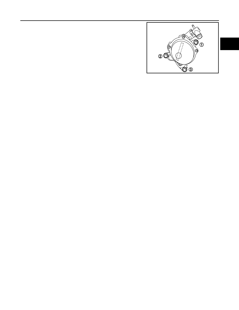
• Tighten mounting bolts in numerical order as shown in the figure.

CAUTION:

Be sure to check that the vacuum pump is in contact with the
cylinder head before tightening the mounting bolts.

E1BIA0614ZZ

EM-402

< REMOVAL AND INSTALLATION >

[R9M]

OIL SEPARATOR

OIL SEPARATOR

Exploded View

INFOID:0000000010281995

Removal and Installation

INFOID:0000000010281996

REMOVAL

1.

Remove fuel injection cover. 

2.

Remove PCV hose.

3.

Disconnect harness connector of fuel injector.

4.

Loosen oil separator insulator mounting bolts.

5.

Remove oil separator.

1.

Oil separator

2.

Oil filler plug

3.

PCV hose

4.

Gasket

5.

Cylinder head

A.

Refer to 

EM-402, "Removal and In-

stallation"

B.

To turbocharger air inlet pipe

Refer to 

GI-4, "Components"

 for symbols in the figure.

E1BIA1209GB

OIL SEPARATOR

EM-403

< REMOVAL AND INSTALLATION >

[R9M]

C

D

E

F

G

H

I

J

K

L

M

A

EM

N

P

O

• Loosen mounting bolts in the reverse order as shown in the

figure.

6.

Remove oil separator insulator.

INSTALLATION

1.

Install gaskets to oil separator.

CAUTION:

Check the gasket is not dropped.

2.

Install oil separator. 
• Tighten mounting bolts in two steps separately in numerical

order as shown in the figure.

3.

Install in the reverse order of removal, for the rest of parts.

: Engine front

E1BIA0610ZZ

: Engine front

1st step: 5.0 N·m (0.51 kg-m, 44 in-lb)

2nd step: 10.0 N·m (1.0 kg-m, 7 ft-lb)

E1BIA0610ZZ

EM-404

< REMOVAL AND INSTALLATION >

[R9M]

INJECTION TUBE AND FUEL INJECTOR

INJECTION TUBE AND FUEL INJECTOR

Exploded View

INFOID:0000000010281997

Removal and Installation

INFOID:0000000010281998

REMOVAL

CAUTION:

• Be sure to read “Precautions for Diesel Equipment”. Refer to 

EM-364, "Precaution for Diesel Equip-

ment"

.

• Wait until the fuel temperature drops before carrying out any work.
• Order the special high pressure injection circuit plug kit.
• It is forbidden to open an fuel injector. If you open an fuel injector by mistake, you will have to

change it.

NOTE:
It is possible to replace a single injection tube.

1.

Oil separator

2.

Fuel injector spacer

3.

Injection tube (center) bolt

4.

Injection rail protector seal

5.

Cylinder head

6.

Fuel hose

7.

Fuel rail pressure sensor

8.

Injection rail protector seal

9.

Injection rail

10. injection rail bolts

11.

Bracket

12. Injection rail protector seal

13. Clip

14. Fuel hose

15. Fuel injector support bolt

16. Fuel return hose

17. Clip

18. Injector

19. Fuel injector support 

20. Injection tube

21. Injection tube (center)

22. Fuel hose

A.

Refer to 

EM-404, "Removal and In-

stallation"

B.

Refer to 

EM-404, "Removal and 

Installation"

C.

To fuel pump

Refer to 

GI-4, "Components"

 for symbols in the figure.

E1BIA1210GB

INJECTION TUBE AND FUEL INJECTOR

EM-405

< REMOVAL AND INSTALLATION >

[R9M]

C

D

E

F

G

H

I

J

K

L

M

A

EM

N

P

O

1.

Remove the battery. Refer to 

PG-155, "Removal and Installation"

.

2.

Remove oil separator. Refer to 

EM-402, "Exploded View"

.

3.

Remove fuel return hose.
• Move without removing the fuel return hose clip using a flate

bade screwdriver.

4.

Disconnect and remove fuel hose. 

5.

Remove fuel collector and injection tube (center).

6.

Remove injection tube (No. 1, 2, 3, 4).
• Put a paint mark or tag on injection tubes to identify each cylinder.

7.

Remove fuel injectors with the following procedure:

a.

Remove fuel injector. While rotating it to left and right, raise it to remove.
• If fuel injector spacer remains in cylinder head, hook it with tip of a flat-bladed screwdriver and pull it out.

CAUTION:

• Handle fuel injector carefully without giving an impact.
• Never disassemble fuel injector.

8.

Remove injection rail and injection rail protector.

9.

CAUTION:

In case of fuel rail pressure sensor fitted with a color ring: 
• replacing the sensor is forbidden
• the injector rail must be completely replaced if the fuel rail pressure sensor fails.

10. Plug all the holes in the injection circuit.

INSTALLATION

1.

If an injector is remplaced, not the IMA code and the corresponding cylinder number and perform "injector
adjustement value registration". Refer to 

EC9-147, "Work Procedure"

.

NOTE:
IMA code are from X1 to XN
After connecting the battery programs the injectors using the diagnostic tool.

2.

Install fuel injector, injection tubes and fuel rail with the following procedure:

a.

Install fuel injector spacer to fuel injector, and insert them into cylinder head.

E1BIA0648ZZ

E1BIA0649ZZ

EM-406

< REMOVAL AND INSTALLATION >

[R9M]

INJECTION TUBE AND FUEL INJECTOR

CAUTION:

• Completely remove any foreign material among fuel injector and cylinder head.

b.

Install injection rail, injection tube (center).
• Finger tighten until contact the injection tube nuts.

c.

Install fuel injector support.

CAUTION:

Be sure to fit fuel injector support without looseness.

d.

NOTE:
In case of cylinder head replacement, pre-tighten the fuel injector support bolt and after loosen the fuel
injector support bolt. 

Tighten fuel injector support bolt.

e.

Turn 180 degrees clockwise (angle tightening).

f.

Install injection tube (No. 1, 2, 3, 4) in the original position (temporarily).
• Finger tighten until contact the injection tube nuts.

CAUTION:

Never put injection tubes under stress.

g.

Tighten injection rail mounting bolts and all injection tube nuts (specified torque).

3.

Install fuel return hose onto fuel injectors with the following procedure.
• NOTE:

Failure to observe the following procedure may lead to an immobilising default.

• Fit the clip on the fuel return hose.
• Install fuel return hose onto fuel injectors.
• Always carry out a "push-pull" test (1), to check that the fuel

return hose is correctly fitted onto fuel injector.

• Always carry out a "push-pull" test, to check that the fuel return

hose is correctly fitted onto fuel hose.

4.

Install in the reverse order of removal, for the rest of parts.

Inspection

INFOID:0000000010281999

INSPECTION AFTER INSTALLATION

• When replacing fuel injector, this procedure must be performed. Refer to 

EC9-143, "Special Repair Require-

ment List"

• When replacing fuel injector, note the injector IMA code and the corresponding cylinder number.  

NOTE:
IMA codes are from X1 to XN.

- Program the injectors using diagnostic tool.

Pre- tightening fuel injec-
tor support bolt (in case of 
cylinder head replace-
ment)

20 Nm (2.0kg-m, 15 ft-lb)

Fuel injector support bolt

7Nm (0.7kg-m, 62 in-lb)

E1BIA0648ZZ

INJECTION TUBE AND FUEL INJECTOR

EM-407

< REMOVAL AND INSTALLATION >

[R9M]

C

D

E

F

G

H

I

J

K

L

M

A

EM

N

P

O

• Start the engine and check for fuel leak for one minute after starting.

CAUTION:

After any operation, check that there are no diesel leaks. Refer to 

EM-364, "Precaution for Diesel

Equipment"

.

E1BIA0649ZZ

EM-408

< REMOVAL AND INSTALLATION >

[R9M]

FUEL PUMP

FUEL PUMP

Exploded View

INFOID:0000000010282000

Removal and Installation

INFOID:0000000010282001

REMOVAL

CAUTION:

• Be sure to read “Precautions for Diesel Equipment”. Refer to 

EM-364, "Precaution for Diesel Equip-

ment"

.

• Wait until the fuel temperature drops before carrying out any work.
• Order the special high pressure injection circuit plug kit.
• Never disassemble or adjust the fuel pump body.

1.

Remove the battery. Refer to 

PG-155, "Removal and Installation"

.

2.

Remove fuel injection cover. 

3.

Remove air duct assembly and air cleaner case. Refer to 

EM-380, "Exploded View"

.

4.

Remove fuel collector. Refer to 

EM-408, "Exploded View"

.

5.

Disconnect fuel hoses from fuel pump. Refer to 

EM-404, "Exploded View"

 and 

EM-404, "Exploded View"

.

6.

Remove the injection tube (center). Refer to 

EM-404, "Exploded View"

.

7.

Plug all the holes of the injection circuit.

8.

Remove the fuel pump.

1.

Fuel pump nut

2.

Fuel pump sprocket

3.

Fuel pump gasket

4.

Fuel collector

5. 

Gasket

6.

Fuel pump

7.

Fuel pump

A.

To fuel tank

B.

To fuel filter

C.

To injection tube (center)

Refer to 

GI-4, "Components"

 for symbols in the figure.

E1BIA0445GB

FUEL PUMP

EM-409

< REMOVAL AND INSTALLATION >

[R9M]

C

D

E

F

G

H

I

J

K

L

M

A

EM

N

P

O

• Loosen mounting bolts in the reverse order as shown in the

figure.

9.

In case of replacement of the fuel pump you need to install the old fuel pump sprocket on the new fuel
pump. Refer to 

EM-410, "Removal and Installation"

.

INSTALLATION

1.

Install fuel pump.

CAUTION:

Be sure to check that the fuel pump is in contact with the cylinder head before tightening the
mounting bolts.
• Tighten mounting bolts in two steps separately in numerical

order as shown in the figure.

2.

Install the injection tube (center). Refer to 

EM-404, "Exploded View"

.

• Finger tighten until contact the injection tube nuts.

3.

Install in the reverse order of removal, for the rest of parts.

4.

Perform "Fuel pump learning value clearing". Refer to 

EC9-158, "Description"

. when replacing fuel pump.

5.

When replacing or removing fuel pump, this procedure must be performed. Refer to 

EC9-143, "Special

Repair Requirement List"

.

Inspection

INFOID:0000000010282002

INSPECTION AFTER INSTALLATION

• Start the engine and check for fuel leak for one minute after starting.

CAUTION:

After any operation, check that there are no diesel leaks. Refer to 

EM-364, "Precaution for Diesel

Equipment"

.

E1BIA0609ZZ

 25.0 N·m (2.6 kg-m, 18 ft-lb)

E1BIA0609ZZ

EM-410

< REMOVAL AND INSTALLATION >

[R9M]

FUEL PUMP SPROCKET

FUEL PUMP SPROCKET

Removal and Installation

INFOID:0000000010282003

REMOVAL

1.

Lock the high pressure fuel pump sprocket on the work-bench in
a vice with protective jaws.

2.

Using the tool [SST (Mot.1906)] (1), lock the high pressure fuel
pump sprocket.

Remove the high pressure fuel pump sprocket nut (2).

3.

Fit a separator (1) from the puller kit under the high pressure
fuel pump sprocket (2).

E1BIA0606ZZ

E1BIA0607ZZ

E1BIA0608ZZ

E1BIA0220ZZ

FUEL PUMP SPROCKET

EM-411

< REMOVAL AND INSTALLATION >

[R9M]

C

D

E

F

G

H

I

J

K

L

M

A

EM

N

P

O

4.

Put the bracket (3) on the separator.

5.

Remove the high pressure fuel pump sprocket. 

INSTALLATION

1.

Refit the sprocket to the newhigh pressure fuel pump.

2.

Screw in the new high pressure fuel pump sprocket on the work bench, without tightening it.

3.

Lock the high pressure fuel pump sprocket on the workbench in a vice with protective jaws.

4.

Torque tighten the high pressure fuel pump sprocket nut.

E1BIA0221ZZ

: 90 N·m (9.2 kg-m, 66 ft-lb)

EM-412

< REMOVAL AND INSTALLATION >

[R9M]

TIMING CHAIN

TIMING CHAIN

Exploded View

INFOID:0000000010282004

1.

Front cover bolt

2.

Front cover 

3.

Exhaust camshaft timing sprocket 
bolts

4.

Timing sprocket spacer

5.

Exhaust camshaft timing sprocket 
(front)

6.

Exhaust camshaft timing sprocket 
(rear) 

7.

Exhaust camshaft

8.

Intake camshaft

9.

Intake camshaft timing sprocket

10. Intake camshaft timing sprocket 

spacer

11.

Intake camshaft timing sprocket bolt 12. Timing chain tensioner guide and 

timing chain guide bolts

13. Crankshaft

14. Timing chain guide

15. Crankshaft sprocket

16. Timing chain

17. Timing chain tensioner guide

18. Timing chain tensioner

19. Timing cover pin

20. Crankshaft spacer

21. Front oil seal

22. Timing chain tensioner bolts

23. Engine mounting bracket (RH)

E1BIA1211GB

TIMING CHAIN

EM-413

< REMOVAL AND INSTALLATION >

[R9M]

C

D

E

F

G

H

I

J

K

L

M

A

EM

N

P

O

NOTE:
Oil pump related parts cannot be removed with an onboard condition. Refer to 

EM-437, "Removal and Instal-

lation"

.

Removal and Installation

INFOID:0000000010282005

REMOVAL

1.

Drain engine oil. Refer to 

LU-49, "Draining"

.

CAUTION:

Perform this step when the engine is cold.

2.

Disconnect the battery cable from the negative terminal.

3.

Remove the following parts:
• Engine undercover
• Load wheel tire (RH)
• Fender protector (RH): Refer to 

EXT-31, "Exploded View"

.

• Drive belt: Refer to 

EM-373, "Removal and Installation"

.

• Fuel filter: Refer to 

FL-46, "Removal and Installation"

.

4.

Remove crankshaft pulley with the following procedure:

a.

Set the crankshaft pulley locking tool [SST: — (Mot. 1770)] (A)
and loosen crankshaft pulley bolt.

b.

Remove crankshaft pulley and spacer.
• Pull crankshaft pulley with both hands to remove it.

CAUTION:

Be careful not to damage front oil seal lip.

5.

Remove front oil seal. Refer to 

EM-427, "FRONT OIL SEAL : Removal and Installation"

.

• Set logs of the service tool (A) the front oil seal notches. Turn

counterclockwise until it locks.

NOTE:
The service tool is supplied in the new front oil seal parts kit.

6.

Remove the through bolt between lower torque rod and engine mounting bracket (rear), and hold the
engine mounting bracket (rear) with a transmission jack. Refer to 

EM-429, "Exploded View"

.

CAUTION:

Never hold the oil pan (lower).

7.

Remove the upper torque rod and the engine mounting insulator (RH). Refer to 

EM-429, "Exploded View"

.

8.

Remove engine mounting bracket and engine mounting stay (front and rear).

9.

Remove water pump pulley. Refer to 

CO-100, "Exploded View"

.

A.

Refer to 

EM-413, "Removal and In-

stallation"

B.

Refer to 

EM-413, "Removal and In-

stallation"

C.

Refer to 

EM-419, "Removal and in-

stallation"

Refer to 

GI-4, "Components"

 for symbols in the figure.

JPBIA0730ZZ

JPBIA0765ZZ

EM-414

< REMOVAL AND INSTALLATION >

[R9M]

TIMING CHAIN

10. Remove front cover with the following procedure:

a.

Loosen front cover mounting bolts.

b.

Use the seal cutter [SST: KV10111100 ( — )] to cut liquid gasket for removal.

CAUTION:

Never use a screwdriver or something similar.
NOTE:
Unstick the front cover by hand, using a jerking motion to ensure it is not damaged.

11. Align the hole (1) on the exhaust camshaft timing sprocket

(front) with the hole (2) on the rocker cover.
• NOTE:

Turn the crankshaft clockwise using the tool [SST: —
(Mot.1770)].

12. Remove the TDC pin plug.
13. In place of plug, manually tighten the tool [SST: —  (Mot.1970)].

14. Turn the crankshaft clockwise until it makes contact with the pin.

15. Make a mark:

• on the intake camshaft timing sprocket (1) and the rocker

cover (2) (vertically).

• on the hole (3) on the exhaust camshaft timing sprocket (front)

and on the rocker cover (4).

• Check the mark alignement (5) and (6).

16. Loosen the exhaust camshaft timing sprocket bolts (front).
17. Compress the timing chain tensioner (1) with timing chain ten-

sioner guide (2), and then insert a stopper pin (A) into hole on
timing chain tensioner.
NOTE:
Use approximately 3.0 mm (0.118 in) dia. hard metal pin as a
stopper pin

E1BIA0586ZZ

E1BIA0589ZZ

E1BIA0590ZZ

JPBIA0727ZZ

TIMING CHAIN

EM-415

< REMOVAL AND INSTALLATION >

[R9M]

C

D

E

F

G

H

I

J

K

L

M

A

EM

N

P

O

18. Remove the timing chain with the following procedure:

a.

the timing hydraulic tensioner,

b.

the timing chain tensioner guide,

c.

the exhaust camshaft timing sprocket bolts,

d.

the timing sprocket spacer,

e.

the crankshaft spacer,

f.

the "Exhaust camshaft timing sprocket (front) - timing chain - crankshaft sprocket" assembly,

g.

the timing chain guide,

h.

the tool [SST: —  (Mot.1970)].

INSTALLATION

1.

Set the engine at TDC.

2.

Install the tool [SST: —  (Mot.1970)].

3.

Install timing chain guide.

4.

Tighten timing chain guide bolts.

5.

Install the crankshaft sprocket onto the crankshaft.

6.

Position:

a.

the timing chain on the crankshaft sprocket (align the sprocket
mark with the cooper chain link (1)).

b.

the timing chain on the exhaust camshaft timing sprocket (front)
(align the sprocket mark with the cooper chain link (1)).

7.

Install the exhaust camshaft timing sprocket (front) onto the exhaust camshaft. 

8.

Place the timing sprocket spacer on the exhaust camshaft timing sprocket (front).

9.

Finger tighten the exhaust camshaft timing sprocket bolts.
NOTE:
Allow the timing sprocket to rotate freely.

10. Install the crankshaft spacer.
11. Install the timing chain tensioner guide.

12. Tighten the bolt of the timing chain tensioner guide.

 Timing chain guide bolts: 25 N·m (2.6 kg-m, 18 

ft-lb)

E1BIA0593ZZ

E1BIA0592ZZ

EM-416

< REMOVAL AND INSTALLATION >

[R9M]

TIMING CHAIN

13. Install the timing hydraulic tensioner with its locking pin.

NOTE:
Check that the hydraulic tensioner is in contact with the cylinder block before tightening the bolts. 

14. Tighten the bolts of the timing hydraulic tensioner.

15. Remove the locking pin.

16. Engage the collet of the tool [SST: —  (Mot.1969)] (15) into the

exhaust camshaft groove.

17. Turn the tool to align the shafts on the spacer and the hole of the rocker cover.

18. Detach the collet of the tool from the exhaust camshaft groove.
19. Engage the pins of the tool in the holes in the intake camshaft timing sprocket.

NOTE:
Do not install the collet of the tool into the groove on the exhaust side of the camshaft.

20. Turn the tool to align the shafts on the spacer and the hole of the rocker cover.

21. Install the collet of the tool into the groove on the exhaust camshaft without forcing it (if necessary, start

the previous operation again).

22. Install the rocker cover onto the tool [SST: —  (Mot.1969)].

23. Tighten the exhaust camshaft timing sprocket bolts.

24. Turn 40 degrees clockwise (angle tightening).

25. Remove: 
a.

the bolts from the tool [SST: —  (Mot.1969)],

b.

the tool [SST: —  (Mot.1969)],

c.

the tool [SST: —  (Mot.1970)],

26. Tighten the TDC hole plug.

 Timing chain tensioner guide bolts: 25 N·m (2.6 

kg-m, 18 ft-lb)

 Timing hydraulic tensioner bolts: 10 N·m (1.0 

kg-m, 7 ft-lb)

E1BIA0594ZZ

 Exhaust camshaft timing sprocket bolts: 10 N·m  

(10 kg-m, 7 ft-lb)

 TDC hole plug: 25 N·m (2.6 kg-m, 18 ft-lb)


Content      ..     24      25      26      27     ..