Qashqai J11. Engine mechanical (HRA2DDT, K9K, MR20DD) - part 12


  Index      Nissan     Qashqai J11. Engine mechanical (HRA2DDT, K9K, MR20DD). Service and Repair Manual


Search            copyright infringement  


Content      ..     10      11      12      13     ..


Qashqai J11. Engine mechanical (HRA2DDT, K9K, MR20DD) - part 12


ENGINE STAND SETTING

EM-177

< UNIT DISASSEMBLY AND ASSEMBLY >

[MR20DD]

C

D

E

F

G

H

I

J

K

L

M

A

EM

N

P

O

UNIT DISASSEMBLY AND ASSEMBLY

ENGINE STAND SETTING

Setting

INFOID:0000000010715492

NOTE:
Explained here is how to disassemble with engine stand supporting transaxle surface. When using different
type of engine stand, note with difference in steps and etc.
1.

Remove the engine and the transaxle assembly from the vehicle, and separate the transaxle from the
engine. Refer to 

TM-35, "Exploded View"

 (MT models) or 

TM-415, "Exploded View"

 (CVT models).

2.

Install engine to engine stand with the following procedure:

a.

Remove flywheel or drive plate. Refer to 

EM-178, "Exploded View"

 or 

EM-181, "Exploded View"

.

b.

Lift the engine with a hoist to install it onto widely use engine stand.

CAUTION:

• Use the engine stand that has a load capacity [approximately 135 kg (298 lb) or more] large

enough for supporting the engine weight. 

• If the load capacity of stand is not adequate, remove the following parts beforehand to reduce the poten-

tial risk of overturning stand.

- Intake manifold: Refer to 

EM-149, "Exploded View"

- Exhaust manifold: Refer to 
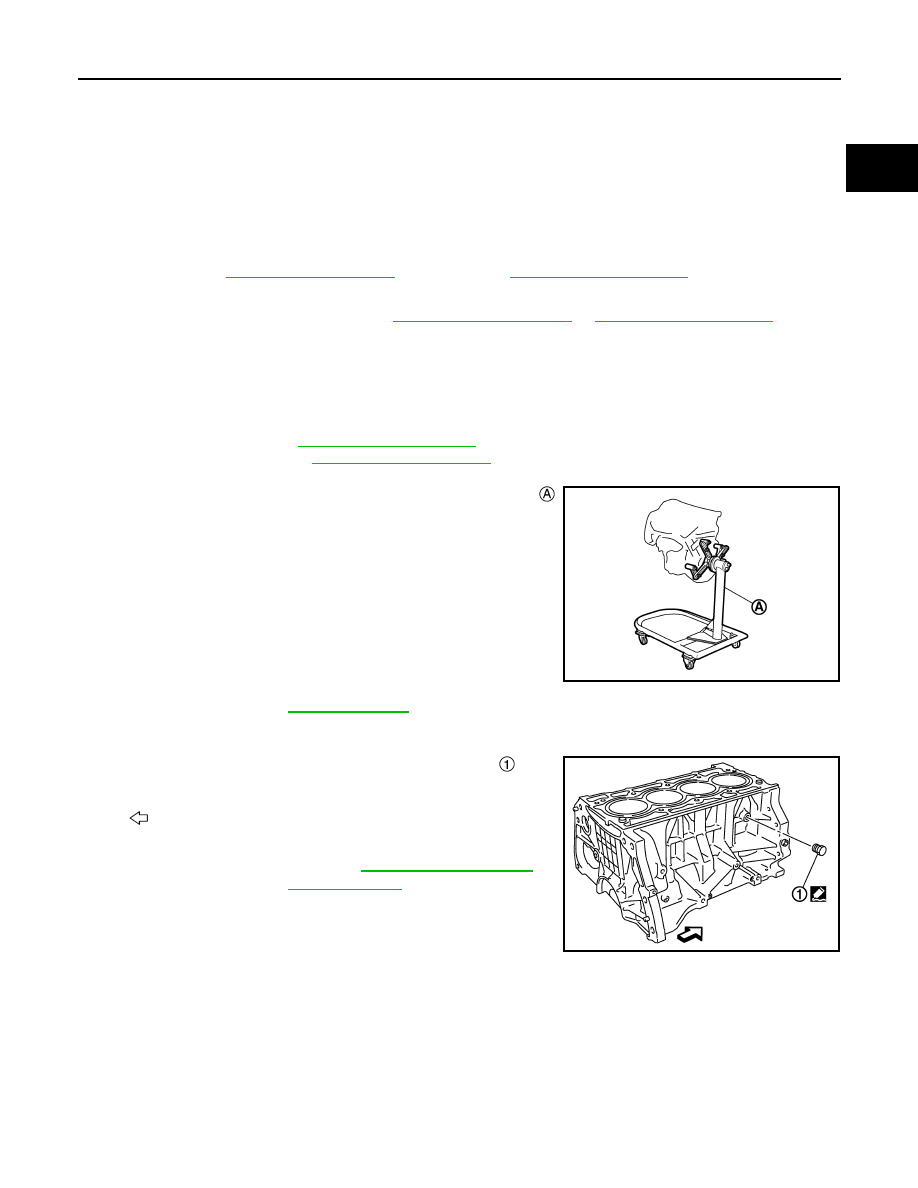
EM-153, "Exploded View"

.

NOTE:
The figure shows an example of widely used engine stand 
that can support mating surface of transaxle with drive plate
removed.

CAUTION:

Before removing the hanging chains, check the engine
stand is stable and there is no risk of overturning.

3.

Drain engine oil. Refer to 

LU-23, "Draining"

.

CAUTION:

Be sure to clean drain plug and install with new drain plug washer.

4.

Drain engine coolant by removing water drain plug 

 from

inside of the engine. 

Use Genuine Liquid Gasket (Three Bond 1217H) or equiva-
lent. 

PBIC3227J

: Engine front

Tightening torque

: Refer to 

EM-223, "Disassembly 

and Assembly"

.

PBIC3228J

EM-178

< UNIT DISASSEMBLY AND ASSEMBLY >

[MR20DD]

FLYWHEEL

FLYWHEEL

Exploded View

INFOID:0000000010715493

Removal and Installation

INFOID:0000000010715494

REMOVAL

1.

Remove the engine and the transaxle assembly from the vehicle, and separate the transaxle from the
engine. Refer to 

EM-172, "Exploded View"

.

2.

Remove flywheel.
• Secure flywheel 

 with a stopper plate [SST: KV11105210]

(A), and remove mounting bolts.

CAUTION:

• Never disassemble them.
• Never place them with signal plate facing down.
• When handling signal plate, take care not to damage or scratch them. 
• Handle signal plate in a manner that prevents them from becoming magnetized.

INSTALLATION

1.

Install flywheel.

Flywheel

: N·m (kg-m, ft-lb)

: Should be lubricated with oil.

JSBIA1437GB

JSBIA1438ZZ

FLYWHEEL

EM-179

< UNIT DISASSEMBLY AND ASSEMBLY >

[MR20DD]

C

D

E

F

G

H

I

J

K

L

M

A

EM

N

P

O

• Secure flywheel 

 with a stopper plate [SST: KV11105210]

(A), and tighten mounting bolts.

• Using TORX socket (size E20), tighten mounting bolts.

CAUTION:

Never damage or scratch and contact surface for clutch disc of flywheel.

Inspection

INFOID:0000000010715495

FLYWHEEL DEFLECTION

• Measure the deflection of flywheel contact surface to torque with a

dial indicator (A).

• Measure the deflection at 210 mm (8.27 in) diameter.

• If measured value is out of the standard, replace flywheel.
• If a trace of burn or discoloration is found on the surface, repair it

with sandpaper.

MOVEMENT AMOUNT OF FLYWHEEL

CAUTION:

Never disassemble double mass flywheel.

Movement Amount of Thrust (Fore-and-Aft) Direction

• Measure the movement amount of thrust (fore-and-aft) direction when 100 N (10.2 kg, 22 lb) force is added

at the portion of 125 mm (4.92 in) radius from the center of flywheel.

• If measured value is out of the standard, replace flywheel.

Movement Amount in Radial (Rotation) Direction

Check the movement amount of radial (rotation) direction with the following procedure:

1.

Install clutch cover mounting bolt 

 to clutch cover mounting

hole, and place a torque wrench (A) on the extended line of the
flywheel  

center 

line.

• Tighten bolt at a force of 9.8 N·m (1.0 kg-m, 87 in-lb) to keep it

from loosening.

2.

Put a mating mark on circumferences of the two flywheel
masses without applying any load (Measurement standard
points).

3.

Apply a force of 

 [9.8 N·m (1.0 kg-m, 87 in-lb)] in each direc-

tion, and mark the movement amount on the mass on the tran-
saxle side.

4.

Measure the dimensions of movement amounts 

 and 

 on circumference of the flywheel on the tran-

saxle side.

JSBIA1438ZZ

Limit  : 0.45 mm (0.0177 in) or less.

JSBIA1439ZZ

Standard

: 1.8 mm (0.071 in) or less

Limit

: 33.2 mm (1.307 in) or less.

JPBIA6915ZZ

EM-180

< UNIT DISASSEMBLY AND ASSEMBLY >

[MR20DD]

FLYWHEEL

• If measured value is out of the standard, replace flywheel.

DRIVE PLATE

EM-181

< UNIT DISASSEMBLY AND ASSEMBLY >

[MR20DD]

C

D

E

F

G

H

I

J

K

L

M

A

EM

N

P

O

DRIVE PLATE

Exploded View

INFOID:0000000010715496

Removal and Installation

INFOID:0000000010715497

REMOVAL

1.

Remove the engine and the transaxle assembly from the vehicle, and separate the transaxle from the
engine. Refer to 

EM-172, "Exploded View"

.

2.

Remove drive plate.
• Secure drive plate 

 with a stopper plate [SST: KV11105210]

(A), and remove mounting bolts.

• Using TORX socket (size E20), loosen mounting bolts.
• loosen mounting bolts in diagonal order.

CAUTION:

• Never disassemble them.

Pilot converter

Drive plate

Reinforcement plate

Crankshaft position sensor 2

Chamfered

: Crankshaft side

: Always replace after every disassembly.

: N·m (kg-m, ft-lb)

: N·m (kg-m, in-lb)

: Should be lubricated with oil.

JPBIA6837GB

JPBIA4425ZZ

EM-182

< UNIT DISASSEMBLY AND ASSEMBLY >

[MR20DD]

DRIVE PLATE

3.

Remove pilot converter 

, from the rear end of the crankshaft.

Use a pilot bush puller (commercial service tool) 

, if neces-

sary.

INSTALLATION

1.

Install drive plate 

, reinforcement plate 

 and pilot converter

 as shown in figure.

• Using a drift of 33 mm (1.30 in) in diameter, press-fit pilot con-

verter into the end of crankshaft until it stops.

CAUTION:

Be careful not to damage or scratch and contact surface for clutch disc of flywheel.

2.

Install drive plate.
• Secure drive plate 

 with a stopper plate [SST: KV11105210]

(A), and remove mounting bolts.

• Using TORX socket (size E20), tighten mounting bolts.
• Install mounting bolts in diagonal order.

Inspection

INFOID:0000000010715498

DRIVE PLATE DEFLECTION

• Measure the deflection of drive plate contact surface to torque con-

verter with a dial indicator (A).

• Measure the deflection at the area limited between 11.0 mm (0.433

in) dia and 20.6 mm (0.811 in) dia around hole 

.

• If measured value is out of the standard, replace drive plate.

PBIC3229J

: Crankshaft rear end

: Rounded

: Chamfered

PBIC3259J

JPBIA4425ZZ

Limit  : 0.20 mm (0.0079 in) or less.

JSBIA1441ZZ

TIMING CHAIN

EM-183

< UNIT DISASSEMBLY AND ASSEMBLY >

[MR20DD]

C

D

E

F

G

H

I

J

K

L

M

A

EM

N

P

O

TIMING CHAIN

Exploded View

INFOID:0000000010715499

Slack guide

Timing chain tensioner

Timing chain

Balancer unit timing chain

Crankshaft sprocket

Crankshaft key

Balancer unit sprocket

Balancer unit timing chain tensioner

O-ring

Timing chain tension guide

Camshaft sprocket (INT)

Camshaft sprocket (EXH)

O-ring

Front cover

Front oil seal

Crankshaft pulley

Crankshaft pulley bolt

O-ring

JPBIA6825GB

EM-184

< UNIT DISASSEMBLY AND ASSEMBLY >

[MR20DD]

TIMING CHAIN

Removal and Installation

INFOID:0000000010715500

REMOVAL

CAUTION:

The rotating direction in the text indicates all directions seen from the engine front.

1.

Drain engine oil. Refer to 

LU-23, "Draining"

.

CAUTION:

Perform this step when engine is cold.

2.

Remove rocker cover. Refer to 

EM-170, "Exploded View"

.

3.

Remove drive belts. Refer to 

EM-139, "Removal and Installation"

.

4.

Set No. 1 cylinder at TDC on its compression stroke with the following procedure:

a.

Rotate crankshaft pulley 

 clockwise and align TDC mark (no

paint) 

 to timing indicator 

 on front cover. 

b.

At the same time, check that the cam noses of the No. 1 cylinder
are located (

) as shown in the figure.

• If not, rotate crankshaft pulley one revolution (360 degrees)

and align as shown in the figure.

5.

Remove crankshaft pulley with the following procedure:

O-ring

VTC cover

O-ring

Exhaust valve timing control solenoid 
valve

Intake valve timing control solenoid valve

Comply with the installation procedure 
when tightening. Refer to 

EM-197, 

"Removal and Installation"

Comply with the installation procedure 
when tightening. Refer to 

EM-184, "Re-

moval and Installation"

: Always replace after every disassembly.

: N·m (kg-m, ft-lb)

: N·m (kg-m, in-lb)

: Should be lubricated with oil.

: Sealing point

: Indicates that the part is connected at points with same symbol in actual vehicle.

: White paint mark (Not use for service)

PBIC3960E

: Camshaft (INT)

: Camshaft (EXH)

: Engine front

JPBIA4347ZZ

TIMING CHAIN

EM-185

< UNIT DISASSEMBLY AND ASSEMBLY >

[MR20DD]

C

D

E

F

G

H

I

J

K

L

M

A

EM

N

P

O

a.

Fix crankshaft pulley 

 with a pulley holder 

 (commercial ser-

vice tool), loosen crankshaft pulley bolt, and locate bolt seating
surface at 10 mm (0.39 in) from its original position.

CAUTION:

Never remove the crankshaft pulley bolt as they will be
used as a supporting point for the pulley puller [SST:
KV11103000].

b.

Attach a pulley puller [SST: KV11103000] 

 in the M6 thread

hole on crankshaft pulley 

, and remove crankshaft pulley. 

6.

Remove oil pan (lower). Refer to 

EM-156, "Exploded View"

.

NOTE:
If crankshaft sprocket and balancer unit component are not removed, this step is unnecessary.

7.

Remove intake valve timing control solenoid valve and exhaust valve timing control solenoid valve.

8.

Remove idler pulley assembly. Refer to 

EM-146, "Exploded View"

.

9.

Remove VTC cover.
• Loosen mounting bolts in the order from 8 to 1 as shown in the

figure.

NOTE:
Disregard No. 6 when loosening.

10. Remove front cover with the following procedure:

PBIC3961E

PBIC3962E

JPBIA6820ZZ

EM-186

< UNIT DISASSEMBLY AND ASSEMBLY >

[MR20DD]

TIMING CHAIN

a.

Loosen mounting bolts in the order from 21 to 1 as shown in the
figure.

b.

Cut liquid gasket by prying the position (

) shown in the figure,

and then remove the front cover.

CAUTION:

• Be careful not to damage the mating surface.
• A more adhesive liquid gasket is applied compared to pre-

vious types when shipped, so it should not be forced off
the position not specified.

11. Remove front oil seal from front cover. 

CAUTION:

Be careful not to damage front cover.
• Lift up front oil seal using a screwdriver.

12. Remove timing chain tensioner with the following procedure:

a.

Push in timing chain tensioner plunger. 

JPBIA6821ZZ

JPBIA4394ZZ

TIMING CHAIN

EM-187

< UNIT DISASSEMBLY AND ASSEMBLY >

[MR20DD]

C

D

E

F

G

H

I

J

K

L

M

A

EM

N

P

O

b.

Insert a stopper pin (A) into the body hole, and then fix it with the
plunger pushed in.

NOTE:
Use approximately 1.5 mm (0.059 in) diameter. hard metal pin
as a stopper pin.

c.

Remove timing chain tensioner.

13. Remove slack guide 

, tension guide 

 and timing chain 

.

CAUTION:

Never rotate each crankshaft and camshaft individually
while timing chain is removed. It causes interference
between valve and piston.

14. Remove crankshaft sprocket and balancer unit drive component with the following procedure:

: Timing chain tensioner

JPBIA4395ZZ

JPBIA5155ZZ

EM-188

< UNIT DISASSEMBLY AND ASSEMBLY >

[MR20DD]

TIMING CHAIN

a.

Press the balancer unit timing chain slack guide 

 toward bal-

ancer unit timing chain tensioner 

.

b.

Insert a stopper pin (A) into tensioner body slit to secure the bal-
ancer unit timing chain slack guide.
NOTE:
Use a hard metal pin with the diameter of approximately 1.5 mm
(0.059 in) as a stopper pin.

c.

Remove balancer unit timing chain tensioner.
• When the holes on lever and tensioner body cannot be

aligned, align these holes by slightly moving the balancer unit
timing chain slack guide.

d.

Hold the WAF part of balancer shaft [WAF: 19 mm (0.75 in)] 

,

and then loosen the balancer unit sprocket bolt.

CAUTION:

• Secure the balancer unit shaft with the WAF part.
• Never loosen the balancer unit sprocket bolt by tightening

the balancer unit drive chain.

e.

Remove crankshaft sprocket, balancer unit sprocket and bal-
ancer unit timing chain as a set.

INSTALLATION

CAUTION:

Do not reuse O-rings.
NOTE:

JPBIA5156ZZ

: Oil pan (upper)

: Engine front

PBIC3168J

TIMING CHAIN

EM-189

< UNIT DISASSEMBLY AND ASSEMBLY >

[MR20DD]

C

D

E

F

G

H

I

J

K

L

M

A

EM

N

P

O

The figure shows the relationship between the matching mark on
each timing chain and that on the corresponding sprocket, with the
components installed.

*: There are two outer grooves in camshaft sprocket (INT). The wider one is a matching mark.

1.

Check that crankshaft key points straight up.

2.

If the tension guide (front cover side) is removed, install it to the front cover.

CAUTION:

Check the joint condition by sound or feeling.

3.

Install crankshaft sprocket 

, balancer unit sprocket 

 and bal-

ancer unit timing chain 

.

• Install it by aligning matching marks on each sprocket and bal-

ancer unit timing chain. 

• If these matching marks are not aligned, rotate the balancer

shaft slightly to correct the position.

CAUTION:

Check matching mark position of each sprocket after installing the balancer unit timing chain.

: Timing chain 

: Camshaft sprocket (EXH)

: Slack guide

: Timing chain tensioner

: Crankshaft sprocket

: Balancer unit timing chain

: Balancer unit sprocket

: Balancer unit timing chain tensioner

: Tension guide

: Camshaft sprocket (INT)

: Matching mark (dark blue link)

: Matching mark (stamping)

: Crankshaft key position (straight up)

: Matching mark (stamping)

: Matching mark (yellow link)

: Matching mark (white link)

: Matching mark (stamping)

: Matching mark (white link)

: Matching mark (dark blue link)

JSBIA5003ZZ

PBIC3171J

EM-190

< UNIT DISASSEMBLY AND ASSEMBLY >

[MR20DD]

TIMING CHAIN

4.

Hold the WAF part of balancer unit shaft [WAF: 19 mm (0.75 in)]

, and then tighten the balancer shaft sprocket bolt.

CAUTION:

• Secure the balancer unit shaft with the WAF part.
• Never loosen the balancer shaft sprocket bolt by tighten-

ing the balancer unit timing chain.

5.

Install balancer unit timing chain tensioner 

.

• Fix the plunger at the most compressed position using a stop-

per pin (A), and then install it.

• Securely pull out (

) the stopper pin after installing the bal-

ancer unit timing chain tensioner.

• Check matching mark position of balancer unit timing chain

and each sprocket again.

: Oil pan (upper)

: Engine front

PBIC3168J

JPBIA5119ZZ

TIMING CHAIN

EM-191

< UNIT DISASSEMBLY AND ASSEMBLY >

[MR20DD]

C

D

E

F

G

H

I

J

K

L

M

A

EM

N

P

O

6.

Align the matching marks of each sprocket with the matching
marks of timing chain.

*: There are 2 outer grooves in camshaft sprocket (INT). The wider one is a
matching mark.

• If these matching marks are not aligned, rotate the camshaft

slightly by holding the hexagonal portion to correct the posi-
tion.

CAUTION:

Check matching mark position of each sprocket and timing
chain again after installing the timing chain.

7.

Install the tension guide 

 and the slack guide 

.

: Camshaft sprocket (EXH)

: Camshaft sprocket (INT)

: Timing chain

: Matching mark (dark blue link)

: Matching mark (stamping)

: Matching mark (yellow link)

: Matching mark (stamping)

JPBIA5153ZZ

: Timing chain

JPBIA5155ZZ

EM-192

< UNIT DISASSEMBLY AND ASSEMBLY >

[MR20DD]

TIMING CHAIN

8.

Install timing chain tensioner 

.

• Fix the plunger at the most compressed position using a stop-

per pin (A), and then install it.

• Securely pull out the stopper pin after installing the timing

chain tensioner.

9.

Check matching mark position of timing chain and each sprocket again.

10. Install front oil seal. Refer to 

EM-206, "FRONT OIL SEAL : Removal and Installation"

.

11. Install front cover with the following procedure:

a.

Install new O-ring to cylinder block. 

CAUTION:

• Do not reuse O-ring.
• Never misalign O-ring.

b.

Apply a continuous bead of liquid gasket (A) with a tube presser
(commercial service tool) to front cover 

 as shown in the fig-

ure. 

Use Genuine Liquid Gasket (Three Bond 1217H) or equiva-
lent.

c.

Check that matching marks of timing chain and each sprocket are still aligned. Then install front cover.

CAUTION:

• Check O-ring on cylinder block is correctly installed.
• Be careful not to damage front oil seal by interference with front end of crankshaft.

JPBIA4395ZZ

: 4.0 - 5.6 mm (0.157 - 0.220 in)

φ

3.4 - 4.4 mm (0.134 - 0.173 in)

: Engine outside

JPBIA6822ZZ


Content      ..     10      11      12      13     ..