Qashqai J11. Engine mechanical (HRA2DDT, K9K, MR20DD) - part 11


  Index      Nissan     Qashqai J11. Engine mechanical (HRA2DDT, K9K, MR20DD). Service and Repair Manual


Search            copyright infringement  


Content      ..     9      10      11      12     ..


Qashqai J11. Engine mechanical (HRA2DDT, K9K, MR20DD) - part 11


HIGH PRESSURE FUEL PUMP AND FUEL HOSE

EM-161

< REMOVAL AND INSTALLATION >

[MR20DD]

C

D

E

F

G

H

I

J

K

L

M

A

EM

N

P

O

7.

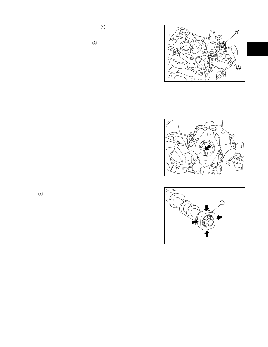
Remove high pressure fuel pump 

 and lifter.

CAUTION:

To prevent damage to high pressure fuel pump and cam-
shaft bracket, loosen bolt 

 alternately by one turn at a

time until the reaction force applied on the high pressure
fuel pump disappears.

INSTALLATION

CAUTION:

• Do not reuse O-rings.
• To prevent damage to parts due to generated abnormal stress and eccentric load, always observe

the installation procedure.

1.

Install high pressure fuel pump according to the following procedure.

a.

Check the orientation of pump cam from the mounting area
(view arrow) of high pressure fuel pump.

b.

Aim pump cam at the BDC area (arrow position).

NOTE:
For BDC area, anywhere within the area indicated by arrow can
be accepted.

c.

Install O-ring to high pressure fuel pump. When handing new O-ring, paying attention to the following cau-
tion items:

CAUTION:

• Do not reuse O-ring.
• Handle O-ring with bare hands. Never wear gloves.
• Lubricate O-ring with new engine oil.
• Never clean O-ring with solvent.
• Check that O-ring and its mating part are free of foreign material.
• Never damage O-ring with tools and fingernails during the installation. In addition, twisting or

stretching O-ring is not allowed. If O-ring is stretched during the installation to high pressure
fuel pump, never install high pressure fuel pump immediately.

d.

Install high pressure fuel pump lifter.

e.

Apply oil to the fitting area of high pressure fuel pump O-ring and camshaft bracket side to install high
pressure fuel pump.

f.

Install high pressure fuel pump. To prevent damage to high pressure fuel pump and camshaft bracket, the
following instructions must be observed.

JSBIA1673ZZ

JPBIA4379ZZ

: Camshaft (EXH)

JPBIA4380ZZ

EM-162

< REMOVAL AND INSTALLATION >

[MR20DD]

HIGH PRESSURE FUEL PUMP AND FUEL HOSE

CAUTION:

• Temporarily tighten bolt 

 by hand. Alternately tighten

bolt by one turn at a time until high pressure fuel pump
reaches camshaft bracket.

• After a pump flange sitting, tighten the bolts to the speci-

fied torque.

2.

Connect fuel feed hose with the following procedure, and them install the fuel feed hose.

a.

Check no foreign substances are deposited in and around matching pipe and quick connector, and no
damage on them.

b.

Quick connector shall be inserted gradually, aligning with the axis of the matching pipe.

c.

Insert the retainer until it clicks and check the retainer is locked.
After insertion, pull the connector and check that the connector
is locked.

CAUTION:

If retainer cannot be installed smoothly, quick connector
may be have not been installed correctly. Check connection
again.

d.

After attaching the quick connector and fix the hose to the clamp.

3.

Install new fuel rail connector 

.

CAUTION:

• Never reuse fuel rail connector.
• Handle O-ring with bare hands. Never wear gloves.
• Lubricate O-ring with new engine oil.
• Never clean O-ring with solvent.
• Check that O-ring and its mating part are free of foreign

material.

• Never scratch O-ring with tools or fingernails when

installing fuel rail connector.

• Insert new fuel rail connector straight into fuel rail. Never decenter or twist the fuel rail connec-

tor during insertion.

4.

Install the fuel tube with the following procedure.

CAUTION:

• When removing fuel tube, always replace fuel rail connector together with fuel tube.
• Never reuse fuel tube.
• Never use fuel tube if its terminal tip is damaged.
• Observe the tightening order and the tightening torque.

: High pressure fuel pump

JSBIA1673ZZ

: Lock position

: Unlock position 

JPBIA4381ZZ

: O-ring

JSBIA1674ZZ

HIGH PRESSURE FUEL PUMP AND FUEL HOSE

EM-163

< REMOVAL AND INSTALLATION >

[MR20DD]

C

D

E

F

G

H

I

J

K

L

M

A

EM

N

P

O

a.

Temporarily tighten flare nut 

 and 

 of fuel tube 

 until

seated.

CAUTION:

When temporarily tightening flare nut, place pipe in the cen-
ter of the nut inner diameter.

b.

Temporarily tighten bolt 

 until the seat of bracket is seated.

c.

Tighten flare nut 

 and 

 in alphabetical order.

CAUTION:

Always fit the tool completely with the nut.

d.

Tighten bolt 

.

5.

Install in the reverse order of removal after this step.

Inspection

INFOID:0000000010715483

INSPECTION AFTER INSTALLATION

Check for Fuel Leakage

1.

Turn ignition switch “ON” (with the engine stopped). With fuel pressure applied to fuel piping, check that
there is no fuel leakage at connection points.
NOTE:
Use mirrors for checking at points out of clear sight.

2.

Start the engine. With engine speed increased, check again that there is no fuel leakage at connection
points.

CAUTION:

Never touch the engine immediately after it is stopped because the engine is extremely hot.

: High pressure fuel pump

: Fuel rail connector

JPBIA5808ZZ

EM-164

< REMOVAL AND INSTALLATION >

[MR20DD]

FUEL INJECTOR AND FUEL TUBE

FUEL INJECTOR AND FUEL TUBE

Exploded View

INFOID:0000000010715484

CAUTION:

• Never remove or disassemble parts unless instructed as shown in the figure.

Removal and Installation

INFOID:0000000010715485

WARNING:

• Be sure to read 

EM-124, "Precaution for Handling High Pressure Fuel System"

 when working on the

high pressure fuel system.

• Put a “CAUTION: FLAMMABLE” sign in the workshop.
• Be sure to work in a well ventilated area and furnish workshop with a CO

2

 fire extinguisher. 

• Never smoke while servicing fuel system. Keep open flames and sparks away from the work area.

Holder

Seal ring (white)

Backup ring

O-ring (blue)

Fuel injector

Stud bolt

Fuel rail

Fuel rail insulator

Fuel rail cover

Fuel pressure sensor

Gasket

To fuel rail connector and fuel tube. 
Refer to 

EM-159

.

Comply with the assembly procedure 
when tightening. Refer to 

EM-164

: N·m (kg-m, ft-lb)

: N·m (kg-m, in-lb)

: Always replace after every disassembly.

: Should be lubricated with oil.

JPBIA5893GB

FUEL INJECTOR AND FUEL TUBE

EM-165

< REMOVAL AND INSTALLATION >

[MR20DD]

C

D

E

F

G

H

I

J

K

L

M

A

EM

N

P

O

• To avoid the danger of being scalded, never drain engine coolant when engine is hot.

REMOVAL

1.

Release the fuel pressure. Refer to 

ECM-135, "Work Procedure"

.

2.

Remove oil level gauge. Refer to 

EM-222, "Exploded View"

.

3.

Remove intake manifold. Refer to 

EM-149, "Exploded View"

.

4.

Remove alternator. Refer to 

CHG-52, "MR20DD : Exploded View"

.

5.

Remove oil level gauge guide. Refer to 

EM-222, "Exploded View"

.

6.

Remove fuel rail cover, and then remove fuel rail insulator.

7.

Remove fuel tube and fuel rail connector. Refer to 

EM-159, "Exploded View"

.

8.

Disconnect fuel pressure sensor harness connector.

9.

Disconnect fuel injector harness connector.

10. Remove fuel pressure sensor, if necessary.
11. Remove fuel rail.

• Loosen mounting bolts in reverse order as shown in the figure.

CAUTION:

• When removing, be careful to avoid any interference with fuel

injector.

• Use a shop cloth to absorb any fuel leakage from fuel rail.

12. Remove fuel injector from cylinder head as per the following.

CAUTION:

• Be careful with remaining fuel that may go out from fuel rail.
• Be careful not to damage injector nozzles during removal.
• Never bump or drop fuel injector.
• Never disassemble fuel injector.

a.

Remove injector holder.

b.

Install an remover [SST: KV10119600 (—)] (A) to the injector
connector side so that cutout 

 of injector remover faces the

injector connector side.

• Hook pawl portion 

 of injector remover [SST: KV10119600

(—)] (A) to groove portion 

 of injector

: Engine front

JPBIA4388ZZ

JPBIA4382ZZ

JSBIA0343ZZ

EM-166

< REMOVAL AND INSTALLATION >

[MR20DD]

FUEL INJECTOR AND FUEL TUBE

c.

Press down body portion of injector remover [SST: KV10119600
(—)] (A) until it contacts cylinder head.

d.

Tighten injector remover [SST: KV10119600 (—)] clockwise and
remove injector from cylinder head.

e.

Cut seal ring 

 while pinching it. Be careful not to damage injec-

tor.

INSTALLATION

CAUTION:

Do not reuse O-rings.

1.

Install seal ring to fuel injector as per the following:

CAUTION:

• Handle seal ring with bare hands. Never wear gloves.
• Never apply engine oil to seal ring.
• Never clean seal ring with solvent.

JPBIA4383ZZ

JPBIA4384ZZ

JSBIA0346ZZ

FUEL INJECTOR AND FUEL TUBE

EM-167

< REMOVAL AND INSTALLATION >

[MR20DD]

C

D

E

F

G

H

I

J

K

L

M

A

EM

N

P

O

a.

Install an injector seal drift set [SST: KV101197S0 (—)] (A) to
fuel injector 

.

b.

Set seal ring 

 to injector seal drift set [SST: KV101197S0 (—)]

c.

Straightly insert seal ring 

, which is set in step 2, to fuel injec-

tor as shown in the figure and install.

CAUTION:

Be careful that seal ring does not exceed the groove portion
of fuel injector.

d.

Insert injector seal drift set [SST: KV101197S0 (—)] (A) to injec-
tor and rotate clockwise and counterclockwise by 90

°

 while

pressing seal ring to fit it.
NOTE:
Compress seal ring, because this operation is for rectifying
stretch of seal ring caused by installation and for preventing
sticking when inserting injector into cylinder head.

2.

Install O-ring and backup ring to fuel injector. When handing new O-ring and backup ring, paying attention
to the following caution items:

CAUTION:

• Do not reuse O-ring.
• Handle O-ring with bare hands. Never wear gloves.
• Lubricate O-ring with new engine oil.
• Never clean O-ring with solvent.
• Check that O-ring and its mating part are free of foreign material.
• When installing O-ring, be careful not to scratch it with tool or fingernails. Also be careful not to

twist or stretch O-ring. If O-ring was stretched while it was being attached, never insert it quickly
into fuel tube.

JPBIA4386ZZ

JSBIA0348ZZ

JSBIA0350ZZ

JSBIA0351ZZ

EM-168

< REMOVAL AND INSTALLATION >

[MR20DD]

FUEL INJECTOR AND FUEL TUBE

• Insert new O-ring straight into fuel rail. Never decenter or twist it.
• Always install the back up ring 

 in the right direction as

instructed.

3.

Install fuel injector 

 to fuel rail 

 as per the following:

a.

Install fuel injector holder 

 to fuel injector.

CAUTION:

• Never reuse fuel injector holder. Replace it with a new

one.

• Be careful to keep fuel injector holder from interfering

with O-ring. If interference occurs, replace O-ring.

b.

Insert fuel injector into fuel rail with fuel injector holder attached.
• Insert it while matching it to the axial center.
• Insert so that protrusion 

 of fuel injector is aligned to cutout

.

c.

Check that installation is complete by checking that fuel injector
does not rotate or come off.
• Check that protrusions of fuel injectors and fuel rail are aligned

with cutouts of clips after installation.

4.

Install fuel rail and fuel injector assembly to cylinder head.
• Tighten mounting bolts and nuts in two steps in numerical

order as shown in the figure.

5.

Connect injector harness connector.

6.

Install fuel pressure sensor, if removed. 

7.

Install fuel rail insulator.

CAUTION:

• As covering part of fuel tube connector at the back end of common rail can easily move because

of its shape, do not remove it before installation.

• Install the insulator so that it is placed under lower side of intake manifold flange.

8.

Install in the reverse order of removal after this step.

JPBIA3864ZZ

: O-ring (blue)

: Backup ring

JPBIA4387ZZ

: Engine front

 1st step

: 10.0 N·m (1.0 kg-m, 89 in-lb)

 2nd step

: 20.5 N·m (2.1 kg-m, 15 ft-lb)

JPBIA4388ZZ

FUEL INJECTOR AND FUEL TUBE

EM-169

< REMOVAL AND INSTALLATION >

[MR20DD]

C

D

E

F

G

H

I

J

K

L

M

A

EM

N

P

O

Inspection

INFOID:0000000010715486

INSPECTION AFTER INSTALLATION

Check on Fuel Leakage

1.

Turn ignition switch “ON” (with the engine stopped). With fuel pressure applied to fuel piping, check there
are no fuel leakage at connection points.
NOTE:
Use mirrors for checking at points out of clear sight.

2.

Start the engine. With engine speed increased, check again that there are no fuel leakage at connection
points.

CAUTION:

Never touch the engine immediately after stopped, as the engine becomes extremely hot.

EM-170

< REMOVAL AND INSTALLATION >

[MR20DD]

IGNITION COIL, SPARK PLUG AND ROCKER COVER

IGNITION COIL, SPARK PLUG AND ROCKER COVER

Exploded View

INFOID:0000000010715487

Removal and Installation

INFOID:0000000010715488

REMOVAL

1.

Remove intake manifold. Refer to 

EM-149, "Exploded View"

.   

2.

Remove PCV valve and PCV hose, if necessary.

Ignition coil

Spark plug

Rocker cover

Rocker cover gasket

Oil filler cap

PCV valve

O-ring

Comply with the installation proce-
dure when tightening. Refer to 

EM-

170

: Always replace after every disassembly.

: N·m (kg-m, ft-lb)

: N·m (kg-m, in-lb)

JPBIA6815GB

IGNITION COIL, SPARK PLUG AND ROCKER COVER

EM-171

< REMOVAL AND INSTALLATION >

[MR20DD]

C

D

E

F

G

H

I

J

K

L

M

A

EM

N

P

O

3.

Remove ignition coil.

CAUTION:

• Never drop or shock ignition coil.
• Never disassemble ignition coil.

4.

Remove rocker cover.
• Loosen bolts in the order from 7 to 1 shown in the figure.

5.

Remove rocker cover gasket from rocker cover.

6.

Use scraper to remove all traces of liquid gasket from camshaft bracket.

CAUTION:

Never scratch or damage the mating surface when cleaning off old liquid gasket.

INSTALLATION

CAUTION:

Do not reuse O-ring.

1.

Install the rocker cover gasket to rocker cover.

CAUTION:

Check the gasket is not dropped.

2.

Install rocker cover.
• Tighten bolts in two steps separately in the order from 1 to 7 as

shown in the figure.

3.

Install in the reverse order of removal, for the rest of parts. 

JPBIA6816ZZ

 1st step

: 1.96 N·m (0.20 kg-m, 17 in-lb)

 2nd step

: 8.33 N·m (0.85 kg-m, 74 in-lb)

JPBIA6816ZZ

EM-172

< UNIT REMOVAL AND INSTALLATION >

[MR20DD]

ENGINE ASSEMBLY

UNIT REMOVAL AND INSTALLATION

ENGINE ASSEMBLY

Exploded View

INFOID:0000000010715489

MT Model

CVT Model

Engine mounting insulator (RH)

Rubber 

Engine mounting insulator (LH) 

Engine mounting frame support (LH)

Engine mounting bracket support 
(LH)

Rear torque rod 

Rear torque rod bracket

: Always replace after every disassembly.

: N·m (kg-m, ft-lb)

E1BIA1177GB

ENGINE ASSEMBLY

EM-173

< UNIT REMOVAL AND INSTALLATION >

[MR20DD]

C

D

E

F

G

H

I

J

K

L

M

A

EM

N

P

O

Removal and Installation

INFOID:0000000010715490

WARNING:

• Situate the vehicle on a flat and solid surface.
• Place chocks at front and back of rear wheels.
• Attach proper slingers and bolts described in PARTS CATALOG if engine slingers are not equipped.

CAUTION:

• Always be careful to work safely, avoid forceful or uninstructed operations.
• Never start working until exhaust system and coolant are cool enough.
• If items or work required are not covered by the engine section, refer to the applicable sections.
• Always use the support point specified for lifting.
• Use either 2-pole lift type or separate type lift as best you can. If board-on type is used for unavoid-

able reasons, support at the rear axle jacking point with a transmission jack or similar tool before
starting work, in preparation for the backward shift of center of gravity.

Engine mounting insulator (RH)

Rear torque rod bracket

Rear torque rod

Engine mounting bracket (LH)

Stud bolt

Engine mounting bracket support 
(LH)

Engine mounting insulator (LH)

: Always replace after every disassembly.

: N·m (kg-m, ft-lb)

E1BIA1178GB

EM-174

< UNIT REMOVAL AND INSTALLATION >

[MR20DD]

ENGINE ASSEMBLY

• For supporting points for lifting and jacking point at rear axle, refer to 

GI-36, "Garage Jack and

Safety Stand and 2-Pole Lift"

.

NOTE:
When removing components such as hoses, tubes/lines, etc., cap or plug openings to prevent fluid from spill-
ing.

REMOVAL

Outline

Remove the engine and the transaxle assembly from the vehicle downward. Separate the engine and the tran-
saxle.

Preparation

1.

Release the fuel pressure. Refer to 

ECM-135, "Work Procedure"

.

2.

Drain engine coolant from radiator. Refer to 

CO-38, "Draining"

.

CAUTION:

• Perform this step when the engine is cold.
• Never spill engine coolant on drive belts.

3.

Remove the following parts.
• Engine under cover.
• Front road wheels and tires: Refer to 

WT-60, "Exploded View"

 (with TPMS) or 

WT-73, "Exploded View"

(without TPMS).

• Front fender protector (RH and LH): Refer to 

EXT-31, "Exploded View"

• Drive belts: Refer to 

EM-139, "Exploded View"

.

• Engine cover.
• Battery: Refer to 

PG-155, "Removal and Installation"

.

• Battery tray: Refer to 

PG-154, "Exploded View"

.

• TCM: Refer to 

TM-391, "Exploded View"

. (CVT models)

• Air duct, air duct assembly, and air cleaner assembly: Refer to 

EM-147, "Exploded View"

.

• Radiator hose (upper and lower): Refer to 

CO-43, "Exploded View"

.

• Exhaust front tube: Refer to 

EX-11, "Exploded View"

.

Engine Room LH

1.

Disconnect all connections of engine harness around the battery, and then temporarily secure the engine
harness into the engine side.

CAUTION:

Protect connectors using a resin bag against foreign materials during the operation.

2.

Disconnect fuel feed tube at engine side.

3.

Disconnect heater hoses

4.

Disconnect control cable from transaxle. Refer to 

TM-385, "Exploded View"

 (CVT models) or 

TM-28,

"Exploded View"

 (MT models).

5.

Remove EVAP hoses. Refer to 

EM-149, "Exploded View"

.

Engine Room RH

1.

Disconnect vacuum hose from intake manifold. Refer to 

EM-149, "Exploded View"

.

2.

Disconnect A/C piping from A/C compressor. Refer to 

HA-33, "Exploded View"

 (Type 1), 

HA-76,

"Exploded View"

 (Type 2), 

HA-123, "Exploded View"

 (Type 3) or 

HA-171, "Exploded View"

 (Type 4).

3.

Disconnect ground cable above the alternator.

Vehicle Underbody

1.

Disconnect steering lower joint at steering gear assembly side, and release steering shaft. Refer to 

ST-12,

"Exploded View"

.

2.

Remove ground cable at transaxle side.

3.

Remove rear propeller shaft. Refer to 

DLN-186, "Exploded View"

. (4WD models)

4.

Remove front wheel sensor (RH and LH) for ABS from steering knuckle. Refer to 

BRC-138, "FRONT

WHEEL SENSOR : Exploded View"

.

5.

Remove lock plate of brake hose from strut. Refer to 

BR-19, "FRONT : Exploded View"

 (LHD models) or

BR-63, "FRONT : Exploded View"

 (RHD models).

ENGINE ASSEMBLY

EM-175

< UNIT REMOVAL AND INSTALLATION >

[MR20DD]

C

D

E

F

G

H

I

J

K

L

M

A

EM

N

P

O

6.

Remove brake caliper assembly with piping connected from steering knuckle. Temporarily secure it on the
vehicle side with a rope to avoid load on it. Refer to the following table:

7.

Disconnect steering outer sockets from steering knuckle. Refer to 

ST-13, "Disassembly and Assembly"

.

8.

Remove front drive shafts (RH and LH). Refer to 

FAX-22, "Exploded View (LH)"

 (2WD models), 

FAX-24,

"Exploded View (RH)"

 (2WD models) or 

FAX-60, "Exploded View (LH)"

 (4WD models), 

FAX-62,

"Exploded View (RH)"

 (4WD models).

NOTE:
Cap or plug openings to prevent fluid from spilling.

9.

Remove rear torque rod.

10. Remove stabilizer connecting rod. Refer to 

FSU-17, "Exploded View"

.

11. Remove front suspension member. Refer to 

FSU-20, "Exploded View"

.

12. Preparation for the separation work of transaxle is as follows:

• Remove transaxle joint bolts which pierce at oil pan (upper) lower rear side. Refer to 

EM-218, "Exploded

View"

.

Removal

1.

Use a manual lift table caddy (commercial service tool) or equiv-
alently rigid tool such as a transmission jack. Securely support
bottom of the engine and the transaxle assembly.

CAUTION:

Put a piece of wood or an equivalent as the supporting sur-
face, secure a completely stable condition.

2.

Remove engine mounting bolts on engine mounting insulator (RH). 
• Loosen mounting bolts in the reverse order as shown in the

figure.

3.

Remove engine mounting insulator (LH) mounting nut 

 to the

transaxle.

4.

Carefully lower jack, or raise lift to remove the engine and the
transaxle assembly. When performing work, observe the follow-
ing caution.

CAUTION:

• Check that no part interferes with the vehicle side.
• Before and during this lifting, always check if any har-

nesses are left connected.

• During the removal, always be careful to prevent the vehi-

cle from falling off the lift due to changes in the center of
gravity.

• If necessary, support the vehicle by setting jack or suitable tool at the rear.

TYPE

Reference

LHD models

BR-37, "BRAKE CALIPER ASSEMBLY : Exploded View"

RHD models

BR-80, "BRAKE CALIPER ASSEMBLY : Exploded View"

JPBIA5146ZZ

: Vehicle front

JPBIA6802ZZ

JPBIA6803ZZ

EM-176

< UNIT REMOVAL AND INSTALLATION >

[MR20DD]

ENGINE ASSEMBLY

Separation

1.

Install engine slinger to front cover front left side 

 and cylinder

head rear right side 

.

2.

Remove starter motor. Refer to 

STR-25, "MR20DD : Exploded View"

.

3.

Lift with a hoist and separate the engine from the transaxle assembly. Refer to 

TM-35, "Exploded View"

(6MT models) or 

TM-415, "Exploded View"

 (CVT models).

INSTALLATION

Note the following, and install in the reverse order of removal.

CAUTION:

• Never allow engine oil to get on engine mounting insulator. Be careful not to damage engine mount-

ing insulator.

• Check that each mounting insulator is seated properly, and tighten mounting nuts and bolts.

Inspection

INFOID:0000000010715491

INSPECTION AFTER INSTALLATION

Inspection for Leakage

The following are procedures for checking fluids leakage, lubricates leakage, and exhaust gases leakage.
• Before starting engine, check oil/fluid levels including engine coolant and engine oil. If less than required

quantity, fill to the specified level. Refer to 

MA-59, "Fluids and Lubricants"

.

• Use procedure below to check for fuel leakage.
- Turn ignition switch “ON” (with engine stopped). With fuel pressure applied to fuel piping, check for fuel leak-

age at connection points.

- Start engine. With engine speed increased, check again for fuel leakage at connection points.
• Run engine to check for unusual noise and vibration.
• Warm up engine thoroughly to check there is no leakage of fuel, exhaust gases, or any oil/fluids including

engine oil and engine coolant.

• Bleed air from lines and hoses of applicable lines, such as in cooling system.
• After cooling down engine, again check oil/fluid levels including engine oil and engine coolant. Refill to the

specified level, if necessary.

Summary of the inspection items:

*: Power steering fluid, brake fluid, etc.

Slinger bolts

: 32.9 N·m (3.4 kg-m, 24 ft-lb)

JPBIA6836ZZ

Items

Before starting engine

Engine running

After engine stopped

Engine coolant

Level

Leakage

Level

Engine oil

Level

Leakage

Level

Transmission / 
transaxle fluid

AT & CVT Models

Leakage

Level / Leakage

Leakage

MT Models

Level / Leakage

Leakage

Level / Leakage

Other oils and fluids*

Level

Leakage

Level

Fuel

Leakage

Leakage

Leakage

Exhaust gases

Leakage


Content      ..     9      10      11      12     ..