Qashqai J11. Engine mechanical (HRA2DDT, K9K, MR20DD) - part 4
IGNITION COIL, SPARK PLUG AND ROCKER COVER
EM-49
< REMOVAL AND INSTALLATION >
[HRA2DDT]
C
D
E
F
G
H
I
J
K
L
M
A
EM
N
P
O
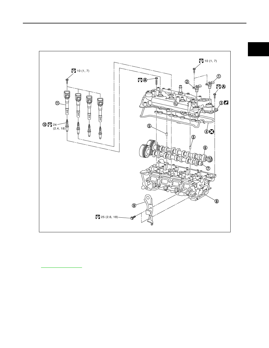
IGNITION COIL, SPARK PLUG AND ROCKER COVER
Exploded View
INFOID:0000000010282226
for symbol marks in the figure.
Removal and Installation
INFOID:0000000010282227
REMOVAL
1.
Camshaft position sensor (EXH)
2.
Camshaft position sensor (INT)
3.
Rocker cover
4.
Rocker cover gasket
5.
Dowel pin
6.
Camshaft (EXH)
7.
Camshaft (INT)
8.
Cylinder head
9.
Engine slinger
10.
Spark plug
11.
Ignition coil
E1BIA1014GB