Qashqai J11. Engine mechanical (HRA2DDT, K9K, MR20DD) - part 2


  Index      Nissan     Qashqai J11. Engine mechanical (HRA2DDT, K9K, MR20DD). Service and Repair Manual


Search            copyright infringement  


Content      ..      1      2      3      ..


Qashqai J11. Engine mechanical (HRA2DDT, K9K, MR20DD) - part 2


DRIVE BELT

EM-17

< PERIODIC MAINTENANCE >

[HRA2DDT]

C

D

E

F

G

H

I

J

K

L

M

A

EM

N

P

O

2.

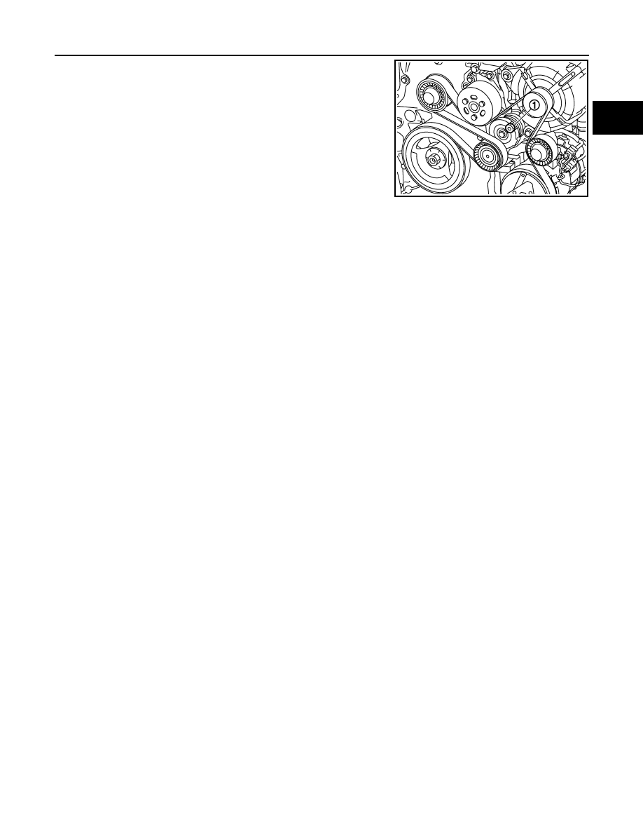
Release the tension on the drive belt by turning drive belt auto-
tensioner (1) clockwise using a 16mm (0.63 in) socket and hold
drive belt auto-tensioner to this position.

3.

Remove drive belt. 

4.

Release the drive belt auto-tensioner until normal position.

CAUTION:

• Clean with a brush the v-block of the crankshaft pulley to remove all dust.

INSTALLATION

1.

Rotate drive belt auto-tensioner clockwise using a 16mm (0.63 in) socket and hold it.

2.

Install drive belt.

CAUTION:

• Check that drive belt is completely set to pulleys.
• Check for engine oil, working fluid and engine coolant are not adhered to drive belt and each pulley

groove. 

3.

Release the drive belt auto-tensioner until drive belt tension is apply.

4.

Turn crankshaft clockwise twice to set drive belt tension on all pulleys.

5.

Install in the reverse order of removal.

E1BIA1000ZZ

EM-18

< PERIODIC MAINTENANCE >

[HRA2DDT]

AIR CLEANER FILTER

AIR CLEANER FILTER

Removal and Installation

INFOID:0000000010282205

REMOVAL

1.

Press the points (A) to separate air resonator from air duct and
air cleaner filter unit.

2.

Remove air resonator following the arrow.

3.

Unhook clips (1) on the air cleaner filter holder.

E1BIA1002ZZ

E1BIA1003ZZ

E1BIA1004ZZ

AIR CLEANER FILTER

EM-19

< PERIODIC MAINTENANCE >

[HRA2DDT]

C

D

E

F

G

H

I

J

K

L

M

A

EM

N

P

O

4.

Separate air cleaner filter holder (1) from air cleaner filter unit
and remove air cleaner filter (2). 

INSTALLATION

Install in the reverse order of removal.

E1BIA1005ZZ

EM-20

< PERIODIC MAINTENANCE >

[HRA2DDT]

SPARK PLUG

SPARK PLUG

Removal and Installation

INFOID:0000000010282206

REMOVAL

1.

Remove ignition coil. Refer to 

EM-49, "Exploded View"

.

2.

Remove spark plug with a spark plug wrench (commercial ser-
vice tool).

CAUTION:

Never drop or shock spark plug.

INSTALLATION

Install in the reverse order of removal.

Inspection

INFOID:0000000010282207

INSPECTION AFTER REMOVAL

Use the standard type spark plug for normal condition.

CAUTION:

• Never drop or shock spark plug.
• Never use a wire brush for cleaning.
• If plug tip is covered with carbon, spark plug cleaner may be

used.

a

: 14 mm (0.55 in)

JPBIA0030ZZ

Spark plug (Standard type)

: Refer to 

EM-114, "Spark Plug"

.

Cleaner air pressure

: Less than 588 kPa (6 kg/cm

2

85 psi)

Cleaning time

: Less than 20 seconds

SMA773C

DRIVE BELT IDLER PULLEY

EM-21

< REMOVAL AND INSTALLATION >

[HRA2DDT]

C

D

E

F

G

H

I

J

K

L

M

A

EM

N

P

O

REMOVAL AND INSTALLATION

DRIVE BELT IDLER PULLEY

Exploded View

INFOID:0000000010282210

Removal and Installation

INFOID:0000000010282211

CAUTION:

• Replace the drive belt that has been removed with a new one.
• Drive belt auto-tensioner, idler pulley and idler roller must be replaced with new ones when the drive

belt is replaced.

• Never run the engine without the drive belt to avoid damaging the crankshaft pulley.

REMOVAL

1.

Remove drive belt. Refer to 

EM-21, "Removal and Installation"

.

2.

Remove drive belt auto-tensioner.

3.

Remove the idler pulley and roller pulley.

4.

Remove multifunction support bracket with the following procedure:

E1BIA1006GB

1.

Multifonction support bracket

2.

Multifonction support bracket bolt

3.

Alternator

4.

Alternator bolt

5.

A/C compressor stud

6.

A/C compressor nut

7.

A/C compressor bolt

8.

A/C compressor 

9.

Cap

10. Idler pulley bolt

11.

Idler pulley 

12. Drive belt auto tensioner

13. Drive belt auto-tensioner bolt

14. Drive belt 

15. Crankshaft pulley bolt

16. Crankshaft pulley

17. Water pump

18. Cap 

19. Idler roller bolt

20. Idler roller

A

Refer  to 

EM-58

Refer to 

GI-4, "Components"

 for symbols in the figure.

EM-22

< REMOVAL AND INSTALLATION >

[HRA2DDT]

DRIVE BELT IDLER PULLEY

a.

Disconnect the battery cable from the negative terminal.

b.

Remove alternator. Refer to 

CHG-28, "HRA2DDT : Removal and Installation"

.

c.

Remove A/C compressor with piping connected from the engine. Temporarily secure it on the vehicule
side with a rope to avoid putting load on it. Refer to 

HA-31, "Removal and Installation"

.

d.

Remove multifunction support bracket

INSTALLATION

1.

Install in the reverse order of removal.

AIR CLEANER AND AIR DUCT

EM-23

< REMOVAL AND INSTALLATION >

[HRA2DDT]

C

D

E

F

G

H

I

J

K

L

M

A

EM

N

P

O

AIR CLEANER AND AIR DUCT

Exploded View

INFOID:0000000010282212

Refer to 

GI-4, "Components"

 for symbol marks in the figure.

Removal and Installation

INFOID:0000000010282213

REMOVAL

1.

Remove air resonator. 

2.

Remove the air duct (inlet).

3.

Remove air cleaner filter unit with air cleaner filter holder assembly.
• Add matching marks if necessary for easier installation.

4.

Disconnect: 
• EVAP vacuum hose from air duct.
• bypass valve hose from air duct.
• wastegate controle valve from air duct.
- Add matching marks if necessary for easier installation.

5.

Remove air duct.

1.

Air cleaner filter

2.

Air resonator

3.

Clip

4.

Air duct (inlet)

5.

Holder

6.

Air cleaner filter unit bracket

7.

Mounting rubber

8.

Clamp 

9.

Air duct

10. Air cleaner filter unit

E1BIA1008GB

EM-24

< REMOVAL AND INSTALLATION >

[HRA2DDT]

AIR CLEANER AND AIR DUCT

6.

Remove air cleaner filter if necessary.

INSTALLATION

Note the following, and install in the reverse order of removal.
• Align marks. Attach each joint. Screw clamps firmly.

Inspection

INFOID:0000000010282214

INSPECTION AFTER REMOVAL

Inspect air duct and resonator assembly for crack or tear.
• If anything found, replace air duct and resonator.

INTAKE MANIFOLD

EM-25

< REMOVAL AND INSTALLATION >

[HRA2DDT]

C

D

E

F

G

H

I

J

K

L

M

A

EM

N

P

O

INTAKE MANIFOLD

Exploded View

INFOID:0000000010282215

Refer to 

GI-4, "Components"

 for symbol marks in the figure.

Removal and Installation

INFOID:0000000010282216

REMOVAL

1.

Remove charge air cooler inlet tube and hose. Refer to 

EM-27, "Exploded View"

.

2.

Disconnect from intake manifold:
• PCV hose.
• EVAP canister purge hose.
• Water outlet vacuum hose.
• Brake booster  hose.

3.

Remove Intake manifold pressure sensor from intake manifold.

4.

Remove oil level gauge.

CAUTION:

Cover the openings to avoid entry of foreign materials.

5.

Remove electric throttle control actuator.

CAUTION:

E1BIA1009GB

1.

Cylinder head

2.

Electric throttle control actuator

3.

O-ring

4.

Intake manifold 

5.

PCV hose

6.

Intake manifold pressure sensor

7.

Vacuum hose

8.

Intake manifold gasket

9.

EVAP canister purge hose bracket

10

EVAP canister purge  hose

A.

To canister purge volume control sole-
noid valve

B.

To air duct

C.

To water outlet

EM-26

< REMOVAL AND INSTALLATION >

[HRA2DDT]

INTAKE MANIFOLD

• Handle electric throttle control actuator carefully and avoid impacts.
• Never disassemble or adjust electric throttle control actuator. 

6.

Remove intake manifold.
• Loosen bolts in the reverse of the order shown in the figure.

INSTALLATION

Note the following, and install in the reverse order of removal.

Intake Manifold

1.

Oil and Install the gasket (A) to the intake manifold.

2.

Place the intake manifold into the installation position.

CAUTION:

Make sure that the oil level gauge guide is not disconnected from the fixing clip of water inlet due
to interference with intake manifold.

3.

Tighten bolts in the numerical order shown in the figure.

Electric Throttle Control Actuator

• Tighten bolts of electric throttle control actuator equally and diagonally in several steps.
• Perform “Throttle Valve Closed Position Learning” after repair when removing harness connector of the elec-

tric throttle control actuator. Refer to 

ECH-102, "Special Repair Requirement List"

.

• Perform “Throttle Valve Closed Position Learning” and “Idle Air Volume Learning” after repair when replacing

electric throttle control actuator. Refer to 

ECH-102, "Special Repair Requirement List"

 and 

ECH-105, "Work

Procedure"

.

E1BIA1028ZZ

E1BIA1034ZZ

E1BIA1028ZZ

CHARGE AIR COOLER

EM-27

< REMOVAL AND INSTALLATION >

[HRA2DDT]

C

D

E

F

G

H

I

J

K

L

M

A

EM

N

P

O

CHARGE AIR COOLER

Exploded View

INFOID:0000000010287252

Refer to 

GI-4, "Components"

 for symbols description.

Removal and Installation

INFOID:0000000010287253

REMOVAL

Air inlet hose

1.

Air inlet hose

2.

Turbocharger

3.

Electric blow off valve hose 1

4.

Blow off valve hose 2

5.

Air inlet tube

6.

Charge air cooler

7.

Mounting rubber

8.

Rocker cover

9.

Turbocharger boost sensor

10. Electric throttle control actuator

11.

Electric blow off valve

12. Cylinder head closing plate

13. Cooling fan

E1BIA1027GB

EM-28

< REMOVAL AND INSTALLATION >

[HRA2DDT]

CHARGE AIR COOLER

1.

Unclip brake booster vacuum hose (1) from air inlet hose. 

2.

Remove charge air inlet hose nuts. Refer to 

EM-27, "Exploded View"

.

3.

Disconnect air inlet hose from turbocharger by pulling on the clip
(1).

4.

Remove engine undercover.

5.

Disconnect air inlet hose from charge aircooler by pulling on
both end (2) of the clip.

6.

Remove air inlet hose.

Air inlet tube.

1.

Remove engine undercover.

2.

Disconnect air inlet tube from charge aircooler by pulling on both
end of the clip (1).

3.

Remove air inlet tube bolt from cooling fan assembly.

4.

Disconnect turbocharger boost sensor.

5.

Disconnect electric blow off valve hose 2 from air inlet tube.

E1BIA1035ZZ

E1BIA1026ZZ

E1BIA1036ZZ

CHARGE AIR COOLER

EM-29

< REMOVAL AND INSTALLATION >

[HRA2DDT]

C

D

E

F

G

H

I

J

K

L

M

A

EM

N

P

O

6.

Remove air inlet tube.

Electric blow off valve.

1.

Remove electric blow off valve hose 1 from air duct.

2.

Remove electric blow off valve hose 2 from air duct from air inlet tube.

3.

Disconnect electric blow off valve connector. 

4.

Unclip vacuum hose from electric blow off valve bracket.

5.

Remove engine slinger and bracket assembly (LH)

6.

Remove electric blow off valve and bracket assmbly bolt. 

7.

Separate electric blow off valve from bracket. 

Charge air cooler.

1.

Remove front bumper. Refer to 

EXT-19, "Exploded View"

.

2.

Put aside front bumper reinforcement (1) with harness assem-
bly.

3.

Remove: 
• Radiator air guide RH (1).
• Radiator air guide LH (2).
• Radiator air guide lower (3).
• Radiator bracket mounting upper (4)

4.

Put aside radiator core support upper. Refer to 

DLK-155, "HRA2DDT : Removal and Installation"


DLK-

155, "HRA2DDT : Removal and Installation"

(Type 1), 

DLK-333, "HRA2DDT : Removal and Installation"

(Type 2), 

DLK-466, "HRA2DDT : Removal and Installation"

 (Type 3), 

DLK-602, "HRA2DDT : Removal and

Installation"

 (Type 4), 

DLK-924, "HRA2DDT : Removal and Installation"

 (Type 6)

E1BIA1038ZZ

E1BIA1037ZZ

EM-30

< REMOVAL AND INSTALLATION >

[HRA2DDT]

CHARGE AIR COOLER

5.

Unhook and rotate charge air cooler (1).

6.

Remove charge air cooler.

CAUTION:

• Avoid interference between the charge air cooler and radiator.
• When removing charge air cooler, close opening on turbo

charger and intake manifold with shop cloth or other suitable
material.

INSTALLATION

Install in the reverse order of removal paying attention to the following points:

CAUTION:

Never reuse O-rings and gasket.
• Pay attention to identification mark and direction.
• Apply a neutral detergent (fluid) to the joint between hoses and pipes (oil is not permissible).
• Pay attention to air flow arrow on the electric blow off valve. 

Inspection

INFOID:0000000010287254

INSPECTION AFTER REMOVAL

1.

Check that the charge air cooler is not full of oil. In that case, clean it with cleaning agent and then let it
dry.

2.

Check air passages of charge air cooler core and fins for clogging, leaks or deformation. Clean or replace
charge air cooler in necessary.
• Never deform core fins.
• For cleaning procedure of charge air cooler core, refer to 

CO-16, "Inspection"

.

E1BIA1039ZZ

CATALYST

EM-31

< REMOVAL AND INSTALLATION >

[HRA2DDT]

C

D

E

F

G

H

I

J

K

L

M

A

EM

N

P

O

CATALYST

Exploded View

INFOID:0000000010287257

Refer to 

GI-4, "Components"

 for symbol marks in the figure.

Removal and Installation

INFOID:0000000010287258

REMOVAL

1.

Remove engine undercover.

2.

Remove A/F sensor 1.
• Using heated oxygen sensor wrench [SST: KV10117100], remove A/F sensor 1.

CAUTION:

Handle A/F sensor 1 carefully and avoid impacts.

3.

Remove A/F sensor 2.
• Using heated oxygen sensor wrench [SST: KV10117100], remove A/F sensor 1.

CAUTION:

Handle A/F sensor 1 carefully and avoid impacts.

E1BIA1023GB

1.

Turbocharger 

2.

A/F sensor 2

3.

A/F sensor 1 harness bracket

4.

Catalyst converter heat shield 

5.

A/F sensor 1 

6.

Catalyst converter 

7.

Gasket

8.

Catalyst converter side bracket

9.

Catalyst converter support bracket

EM-32

< REMOVAL AND INSTALLATION >

[HRA2DDT]

CATALYST

4.

Remove catalyst converter heat shield.

5.

Remove front tube. Refer to 

EX-6, "Exploded View"

6.

Remove nuts of catalyst converter turbocharger side. 

7.

Remove catalyst converter side bracket.

8.

Remove catalyst converter.

9.

Remove catalyst converter gasket.

10. Remove catalyst converter support bracket.

INSTALLATION

1.

Install new gasket between turbocharger and catalyst.

2.

Note the following, and install in the reverse order of removal.
A/F sensor 1
A/F sensor 2
• Using heated oxygen sensor wrench [SST: KV10117100], install A/F sensors.

CAUTION:

Prevent rust preventives from adhering to the sensor body.


Content      ..      1      2      3      ..