Qashqai J11. Engine control system (MR20DD) - part 24


  Index      Nissan     Qashqai J11. Engine control system (MR20DD). Service and Repair Manual


Search            copyright infringement  


Content      ..     22      23      24      25     ..


Qashqai J11. Engine control system (MR20DD) - part 24


ECM-370

< DTC/CIRCUIT DIAGNOSIS >

[MR20DD]

P2138 APP SENSOR

Is the inspection result normal?

YES

>> GO TO 10.

NO

>> Repair or replace malfunctioning part.

10.

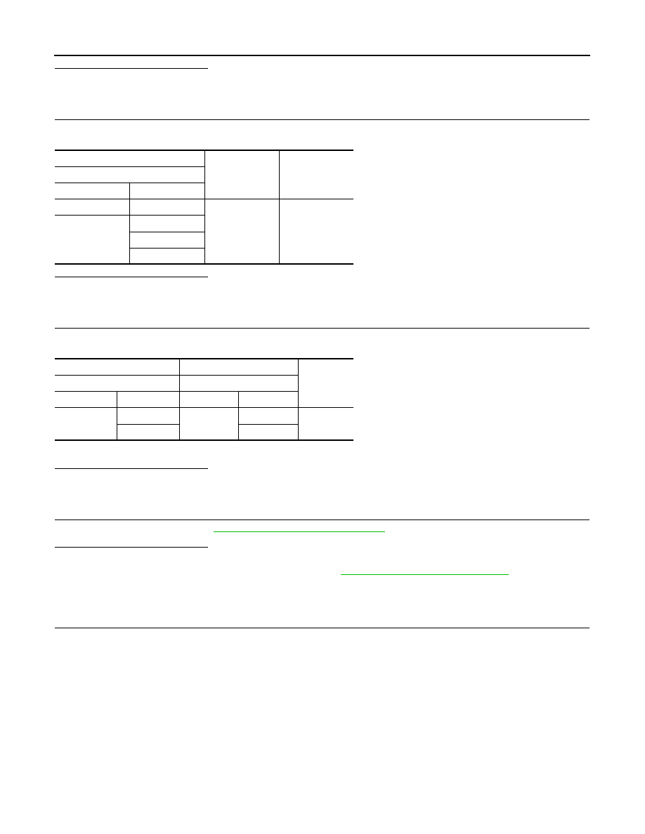
CHECK ECM GROUND CIRCUIT

Check the continuity between ECM harness connector and ground.

Is the inspection result normal?

YES

>> INSPECTION END

NO

>> Repair or replace malfunctioning part.

11.

CHECK APP SENSOR INPUT SIGNAL CIRCUIT

1.

Check the continuity between APP sensor harness connector and ECM harness connector.

2.

Also check harness for short to ground and to power.

Is the inspection result normal?

YES

>> GO TO 12.

NO

>> Repair or replace malfunctioning part.

12.

CHECK APP SENSOR

Check the APP sensor. Refer to 

ECM-370, "Component Inspection"

.

Is the inspection result normal?

YES

>> INSPECTION END

NO

>> Replace accelerator pedal assembly. Refer to 

ACC-3, "Removal and Installation"

.

Component Inspection

INFOID:0000000010703058

1.

CHECK ACCELERATOR PEDAL POSITION SENSOR

1.

Turn ignition switch OFF.

2.

Reconnect all harness connectors disconnected.

3.

Turn ignition switch ON.

4.

Check the voltage between ECM harness connector terminals as per the following condition.

+

Continuity

ECM

Connector

Terminal

F15

11

Ground

Existed

E57

123

125

128

+

Continuity

APP sensor

ECM

Connector

Terminal

Connector

Terminal

E20

3

E57

126

Existed

6

119

P2138 APP SENSOR

ECM-371

< DTC/CIRCUIT DIAGNOSIS >

[MR20DD]

C

D

E

F

G

H

I

J

K

L

M

A

ECM

N

P

O

Is the inspection result normal?

YES

>> INSPECTION END

NO

>> Replace accelerator pedal assembly. Refer to 

ACC-3, "Removal and Installation"

.

ECM

Condition

Voltage

Connector

+

Terminal

E57

126

127

Accelerator pedal

Fully released

0.6 - 0.9 V

Fully depressed

3.9 - 4.7 V

119

120

Fully released

0.3 - 0.6 V

Fully depressed

1.95 - 2.4 V

ECM-372

< DTC/CIRCUIT DIAGNOSIS >

[MR20DD]

FUEL INJECTOR

FUEL INJECTOR

Component Function Check

INFOID:0000000010703059

1.

INSPECTION START

Turn ignition switch to START.
Are any cylinders ignited?

YES

>> GO TO 2.

NO

>> Proceed to 

ECM-372, "Diagnosis Procedure"

.

2.

CHECK FUEL INJECTOR FUNCTION

With CONSULT

1.

Start engine.

2.

Perform “POWER BALANCE” in “ACTIVE TEST” mode with CONSULT.

3.

Check that each circuit produces a momentary engine speed drop.

Without CONSULT

1.

Start engine and let it idle.

2.

Listen to each fuel injector operating sound.

Is the inspection result normal?

YES

>> INSPECTION END

NO

>> Proceed to 

ECM-372, "Diagnosis Procedure"

.

Diagnosis Procedure

INFOID:0000000010703060

1.

CHECK FUEL INJECTOR POWER SUPPLY

1.

Turn ignition switch OFF.

2.

Disconnect fuel injector harness connector.

3.

Turn ignition switch ON.

4.

Check the voltage between fuel injector harness connector and ground.

Is the inspection result normal?

YES

>> GO TO 9.

NO

>> GO TO 2.

2.

CHECK FUEL INJECTOR POWER SUPPLY CIRCUIT

1.

Turn ignition switch OFF.

2.

Disconnect ECM harness connector.

3.

Check the continuity between fuel injector harness connector and ECM harness connector.

Clicking sound should be heard.

PBIB3332E

+

Voltage

Fuel injector

Cylinder

Connector

Terminal

1

F29

1

Ground

Battery voltage

2

F30

1

3

F31

1

4

F32

1

FUEL INJECTOR

ECM-373

< DTC/CIRCUIT DIAGNOSIS >

[MR20DD]

C

D

E

F

G

H

I

J

K

L

M

A

ECM

N

P

O

4.

Also check harness for short to power.

Is the inspection result normal?

YES

>> GO TO 3.

NO

>> Repair or replace malfunctioning part.

3.

CHECK FUEL INJECTOR DRIVER POWER SUPPLY

1.

Disconnect ECM harness connector.

2.

Turn ignition switch ON.

3.

Check the continuity between ECM harness connector and ground.

Is the inspection result normal?

YES

>> Check intermittent incident. Refer to 

GI-41, "Intermittent Incident"

.

NO

>> GO TO 4.

4.

CHECK FUEL INJECTOR DRIVER POWER SUPPLY CIRCUIT

1.

Turn ignition switch OFF.

2.

Disconnect ECM harness connector.

3.

Disconnect fuel injector relay harness connector.

4.

Check the continuity between ECM harness connector and fuel injector relay harness connector.

5.

Also check harness for short to power.

Is the inspection result normal?

YES

>> GO TO 5.

NO

>> Repair or replace malfunctioning part.

5.

CHECK FUEL INJECTOR RELAY POWER SUPPLY (CONTACT SIDE)

Check the voltage between fuel injector relay harness connector and ground.

+

Continuity

Fuel injector

ECM

Cylinder

Connector

Terminal

Connector

Terminal

1

F29

1

F15

1

Existed

2

F30

1

2

3

F31

1

3

4

F32

1

4

+

Voltage

ECM

Connector

Terminal

F16

49

Ground

Battery voltage

53

+

Continuity

ECM

Fuel injector relay

Connector

Terminal

Connector

Terminal

F16

49

F49

5

Existed

53

7

+

Voltage

Fuel injector relay

Connector

Terminal

F49

3

Ground

Battery voltage

6

ECM-374

< DTC/CIRCUIT DIAGNOSIS >

[MR20DD]

FUEL INJECTOR

Is the inspection result normal?

YES

>> GO TO 6.

NO

>> Perform trouble diagnosis for power supply circuit.

6.

CHECK FUEL INJECTOR RELAY POWER SUPPLY (EXCITATION COIL SIDE)

1.

Install all removed parts.

2.

Turn ignition switch ON.

3.

Check the voltage between fuel injector relay harness connector and ground.

Is the inspection result normal?

YES

>> GO TO 8.

NO

>> GO TO 7.

7.

CHECK FUEL INJECTOR RELAY POWER SUPPLY (EXCITATION COIL SIDE)

1.

Turn ignition switch OFF.

2.

Disconnect fuel injector relayharness connector.

3.

Disconnect IPDM E/R harness connector.

4.

Check the continuity between IPDM E/R harness connector and fuel injector relay harness connector.

5.

Also check harness for short to power.

Is the inspection result normal?

YES

>> Perform trouble diagnosis for power supply circuit.

NO

>> Repair or replace malfunctioning part.

8.

CHECK FUEL INJECTOR RELAY GROUND CIRCUIT

1.

Turn ignition switch OFF.

2.

Disconnect fuel injector relay harness connector.

3.

Check the continuity between fuel injector relay harness connector and ground.

4.

Also check harness for short to ground.

Is the inspection result normal?

YES

>> GO TO 10.

NO

>> Repair or replace malfunctioning part.

9.

CHECK FUEL INJECTOR GROUND CIRCUIT

1.

Turn ignition switch OFF.

2.

Disconnect ECM harness connector.

3.

Check the continuity between fuel injector harness connector and ECM harness connector.

+

Voltage

Fuel injector relay

Connector

Terminal

F49

1

Ground

Battery voltage

+

Continuity

IPDM E/R

Fuel injector relay

Connector

Terminal

Connector

Terminal

F90

96

F49

1

Existed

+

Continuity

Fuel injector relay

Connector

Terminal

F49

2

Ground

Existed

FUEL INJECTOR

ECM-375

< DTC/CIRCUIT DIAGNOSIS >

[MR20DD]

C

D

E

F

G

H

I

J

K

L

M

A

ECM

N

P

O

4.

Also check harness for short to ground.

Is the inspection result normal?

YES

>> GO TO 11.

NO

>> Repair or replace malfunctioning part.

10.

CHECK FUEL INJECTOR RELAY

Check fuel injector relay. Refer to 

ECM-375, "Component Inspection (Fuel Injector Relay)"

.

Is the inspection result normal?

YES

>> Check intermittent incident. Refer to 

GI-41, "Intermittent Incident"

.

NO

>> Replace fuel injector relay.

11.

CHECK FUEL INJECTOR

Check fuel injector. Refer to 

ECM-375, "Component Inspection (Fuel Injector)"

.

Is the inspection result normal?

YES

>> Check intermittent incident. Refer to 

GI-41, "Intermittent Incident"

.

NO

>> Replace fuel injector. Refer to 

EM-164, "Removal and Installation"

.

Component Inspection (Fuel Injector)

INFOID:0000000010703061

1.

CHECK FUEL INJECTOR

1.

Turn ignition switch OFF.

2.

Disconnect fuel injector harness connector.

3.

Check the resistance between fuel injector terminals.

Is the inspection result normal?

YES

>> INSPECTION END

NO

>> Replace fuel injector relay.

Component Inspection (Fuel Injector Relay)

INFOID:0000000010703062

1.

CHECK FUEL INJECTOR RELAY

1.

Turn ignition switch OFF.

2.

Remove fuel injector relay.

+

Continuity

Fuel injector

ECM

Cylinder

Connector

Terminal

Connector

Terminal

1

F29

2

F15

5

Existed

2

F30

2

6

3

F31

2

7

4

F32

2

8

Fuel injector

Resistance

(Approx.)

+

Terminal

1

2

1.44 – 1.73 

 [at 10 – 60

°

C (50 –140

°

F)]

ECM-376

< DTC/CIRCUIT DIAGNOSIS >

[MR20DD]

FUEL INJECTOR

3.

Check the continuity between fuel injector relay terminals as per
the following conditions. 

Is the inspection result normal?

YES

>> INSPECTION END

NO

>> Replace fuel injector relay.

+

Condition

Continuity

Fuel injector relay

Terminal

3

5

12 V direct current supply between ter-
minals 1 and 2

Existed

No current supply

Not existed

6

7

12 V direct current supply between ter-
minals 1 and 2

Existed

No current supply

Not existed

JSBIA1178ZZ

LOW PRESSURE FUEL PUMP

ECM-377

< DTC/CIRCUIT DIAGNOSIS >

[MR20DD]

C

D

E

F

G

H

I

J

K

L

M

A

ECM

N

P

O

LOW PRESSURE FUEL PUMP

Component Function Check

INFOID:0000000010703063

1.

CHECK LOW PRESSURE FUEL PUMP FUNCTION

1.

Turn ignition switch ON.

2.

Pinch fuel feed hose 

 with two fingers.

Is the inspection result normal?

YES

>> INSPECTION END

NO

>> Proceed to 

ECM-377, "Diagnosis Procedure"

.

Diagnosis Procedure

INFOID:0000000010703064

1.

CHECK FUEL PUMP RELAY POWER SUPPLY

1.

Turn ignition switch OFF.

2.

Disconnect ECM harness connector.

3.

Turn ignition switch ON.

4.

Check the voltage between ECM harness connector terminals.

Is the inspection result normal?

YES

>> GO TO 3.

NO

>> GO TO 2.

2.

CHECK FUEL PUMP RELAY POWER SUPPLY CIRCUIT

1.

Turn ignition switch OFF.

2.

Disconnect IPDM E/R harness connector.

3.

Check the continuity between ECM harness connector and IPDM E/R harness connector.

4.

Also check harness for short to power.

Is the inspection result normal?

YES

>> Perform trouble diagnosis for power supply circuit.

NO

>> Repair or replace malfunctioning part.

3.

CHECK FUEL PUMP POWER SUPPLY

1.

Turn ignition switch OFF.

2.

Reconnect ECM harness connector.

3.

Disconnect “fuel level sensor unit and fuel pump” harness connector. 

4.

Turn ignition switch ON.

5.

Check the voltage between “fuel level sensor unit and fuel pump” harness connector and ground.

Fuel pressure pulsation should be felt on the fuel 
feed hose for 1 second after ignition switch is 
turned ON.

JSBIA0601ZZ

+

Voltage

ECM

Connector

Terminal

Connector

Terminal

F16

87

E57

128

Battery voltage

+

Continuity

ECM

IPDM E/R

Connector

Terminal

Connector

Terminal

F16

87

F90

106

Existed

ECM-378

< DTC/CIRCUIT DIAGNOSIS >

[MR20DD]

LOW PRESSURE FUEL PUMP

Is the inspection result normal?

YES

>> GO TO 5.

NO

>> GO TO 4.

4.

CHECK FUEL PUMP POWER SUPPLY CIRCUIT

1.

Turn ignition switch OFF.

2.

Disconnect  IPDM E/R harness connector.

3.

Check the continuity between “fuel level sensor unit and fuel pump” harness connector and IPDM E/R
harness connector. 

4.

Also check harness for short to power.

Is the inspection result normal?

YES

>> Perform trouble diagnosis for power supply circuit.

NO

>> Repair or replace malfunctioning part.

5.

CHECK FUEL PUMP GROUND CIRCUIT

1.

Turn ignition switch OFF.

2.

Check the continuity between “fuel level sensor unit and fuel pump” harness connector and ground.

3.

Also check harness for short to ground and to power.

Is the inspection result normal?

YES

>> GO TO 6.

NO

>> Repair or replace malfunctioning part.

6.

CHECK FUEL PUMP

Check fuel pump. Refer to 

ECM-378, "Component Inspection (Fuel Pump)"

.

Is the inspection result normal?

YES

>> Check intermittent incident. Refer to 

GI-41, "Intermittent Incident"

.

NO

>> Replace “fuel level sensor unit and fuel pump”. Refer to 

FL-19, "Removal and Installation"

.

Component Inspection (Fuel Pump)

INFOID:0000000010703065

1.

CHECK FUEL PUMP

1.

Turn ignition switch OFF.

2.

Disconnect “fuel level sensor unit and fuel pump” harness connector. 

3.

Check the resistance between “fuel level sensor unit and fuel pump” terminals as follows.

+

Voltage

Fuel level sensor unit and fuel 

pump

Connector

Terminal

B72

1

Ground

Battery voltage should exist 1 second after igni-
tion switch is turn ON.

+

Continuity

Fuel level sensor unit and fuel 

pump

IPDM E/R

Connector

Terminal

Connector

Terminal

B72

1

E39

48

Existed

+

Continuity

Fuel level sensor unit and fuel pump

Connector

Terminal

B72

3

Ground

Existed

LOW PRESSURE FUEL PUMP

ECM-379

< DTC/CIRCUIT DIAGNOSIS >

[MR20DD]

C

D

E

F

G

H

I

J

K

L

M

A

ECM

N

P

O

Is the inspection result normal?

YES

>> INSPECTION END

NO

>> Replace “fuel level sensor unit and fuel pump”. Refer to 

FL-19, "Removal and Installation"

.

Fuel level sensor unit and fuel pump

Resistance

+

Terminal

1

3

0.2 - 5.0 

 [at 25

°

C (77

°

F)]

ECM-380

< DTC/CIRCUIT DIAGNOSIS >

[MR20DD]

HIGH PRESSURE FUEL PUMP

HIGH PRESSURE FUEL PUMP

Component Function Check

INFOID:0000000010703066

1.

CHECK HIGH PRESSURE FUEL PUMP FUNCTION

With CONSULT

1.

Start engine.

2.

Select “FUEL PRES SEN V” in “DATA MONITOR” mode of “ENGINE” using CONSULT and check the
indication as per the following conditions.

Without CONSULT

1.

Start engine.

2.

Check the voltage between ECM terminals as per the following conditions.

Is the inspection result normal?

YES

>> INSPECTION END

NO

>> Proceed to 

ECM-380, "Diagnosis Procedure"

.

Diagnosis Procedure

INFOID:0000000010703067

1.

CHECK HIGH PRESSURE FUEL PUMP POWER SUPPLY

1.

Turn ignition switch ON.

2.

Check the voltage between ECM harness connector and ground.

Is the inspection result normal?

Monitor item

Condition

Indication

FUEL PRES SEN V

At idle

820 - 1,140 mV

Revving engine up to 4,000 rpm quickly.

820 - 2,900 mV

ECM

Condition

Voltage

Voltage

+

Terminal

F16

51

52

[Engine is running]
• Warm-up condition
• Idle speed

NOTE:
The pulse cycle changes depending on 
rpm at idle.

Battery voltage

(11 - 14 V)  

[Engine is running]
• Warm-up condition
• Engine speed: 2,000 rpm

Battery voltage

(11 - 14 V)  

JPBIA4722ZZ

JPBIA4723ZZ

+

Voltage

ECM

Connector

Terminal

F16

50

Ground

Battery voltage

HIGH PRESSURE FUEL PUMP

ECM-381

< DTC/CIRCUIT DIAGNOSIS >

[MR20DD]

C

D

E

F

G

H

I

J

K

L

M

A

ECM

N

P

O

YES

>> GO TO 8.

NO

>> GO TO 2.

2.

CHECK HIGH PRESSURE FUEL PUMP POWER SUPPLY CIRCUIT

1.

Turn ignition switch OFF.

2.

Disconnect ECM harness connector.

3.

Disconnect high pressure fuel pump relay harness connector.

4.

Check the continuity between ECM harness connector and high pressure fuel pump relay harness con-
nector.

5.

Also check harness for short to power.

Is the inspection result normal?

YES

>> GO TO 3.

NO

>> Repair or replace malfunctioning part.

3.

CHECK HIGH PRESSURE FUEL PUMP RELAY POWER SUPPLY (CONTACT SIDE)

Check the voltage between high pressure fuel pump relay harness connector and ground.

Is the inspection result normal?

YES

>> GO TO 4.

NO

>> Perform the trouble diagnosis for power supply circuit.

4.

CHECK HIGH PRESSURE FUEL PUMP RELAY POWER SUPPLY (EXCITATION COIL SIDE)

1.

Install all removed parts.

2.

Turn ignition switch ON.

3.

Check the voltage between high pressure fuel pump relay harness connector and ground.

Is the inspection result normal?

YES

>> GO TO 6.

NO

>> GO TO 5.

5.

CHECK HIGH PRESSURE FUEL PUMP RELAY POWER SUPPLY CIRCUIT (EXCITATION COIL SIDE)

1.

Turn ignition switch OFF.

2.

Disconnect high pressure fuel pump relay harness connector.

3.

Disconnect IPDM E/R harness connector.

4.

Check the continuity between IPDM E/R harness connector and high pressure fuel pump relay harness
connector.

+

Continuity

ECM

High pressure fuel pump relay

Connector

Terminal

Connector

Terminal

F16

50

F161

5

Existed

+

Voltage

High pressure fuel pump relay

Connector

Terminal

F161

3

Ground

Battery voltage

+

Voltage

High pressure fuel pump relay

Connector

Terminal

F161

1

Ground

Battery voltage

ECM-382

< DTC/CIRCUIT DIAGNOSIS >

[MR20DD]

HIGH PRESSURE FUEL PUMP

5.

Also check harness for short to power.

Is the inspection result normal?

YES

>> Perform the trouble diagnosis for power supply circuit.

NO

>> Repair or replace malfunctioning part.

6.

CHECK HIGH PRESSURE FUEL PUMP RELAY GROUND CIRCUIT

1.

Turn ignition switch OFF.

2.

Disconnect high pressure fuel pump relay harness connector.

3.

Check the continuity between high pressure fuel pump relay harness connector and ground.

4.

Also check harness for short to ground.

Is the inspection result normal?

YES

>> GO TO 7.

NO

>> Repair or replace malfunctioning part.

7.

CHECK HIGH PRESSURE FUEL PUMP RELAY

Check high pressure fuel pump relay. Refer to 

ECM-384, "Component Inspection (High Pressure Fuel Pump

Relay)"

.

Is the inspection result normal?

YES

>> GO TO 8.

NO

>> Replace high pressure fuel pump relay. Refer to 

ECM-103, "Wiring Diagram"

 for connector num-

ber, 

PG-103, "LHD : Engine Room Harness"

 (LHD) 

PG-120, "RHD : Engine Room Harness"

(RHD) for relay location.

8.

CHECK HIGH PRESSURE FUEL PUMP CIRCUIT

1.

Turn ignition switch OFF.

2.

Disconnect ECM harness connector and high pressure fuel pump relay harness connector.

3.

Check the continuity between ECM harness connector and high pressure fuel pump harness connector.

4.

Also check harness for short to power.

Is the inspection result normal?

YES

>> GO TO 9.

NO

>> Repair or replace malfunctioning part.

9.

CHECK HIGH PRESSURE FUEL PUMP

Check high pressure fuel pump. Refer to 

ECM-383, "Component Inspection (High Pressure Fuel Pump)"

.

Is the inspection result normal?

YES

>> GO TO 10.

NO

>> Replace high pressure fuel pump. Refer to 

EM-159, "Removal and Installation"

.

+

Continuity

IPDM E/R

High pressure fuel pump relay

Connector

Terminal

Connector

Terminal

F90

96

F161

1

Existed

+

Continuity

High pressure fuel pump relay

Connector

Terminal

F161

2

Ground

Existed

+

Continuity

ECM

High pressure fuel pump

Connector

Terminal

Connector

Terminal

F16

51

F161

1

Existed

52

2

HIGH PRESSURE FUEL PUMP

ECM-383

< DTC/CIRCUIT DIAGNOSIS >

[MR20DD]

C

D

E

F

G

H

I

J

K

L

M

A

ECM

N

P

O

10.

CHECK HIGH PRESSURE FUEL PUMP INSTALLATION

1.

Turn ignition switch OFF.

2.

Check high pressure fuel pump for improper attachment or looseness.

Is the inspection result normal?

YES

>> GO TO 11.

NO

>> Repair or replace malfunctioning part.

11.

CHECK CAMSHAFT

1.

Remove camshaft. Refer to 

EM-197, "Removal and Installation"

.

2.

Check camshaft. Refer to 

EM-200, "Inspection"

.

Is the inspection result normal?

YES

>> Check intermittent incident. Refer to 

GI-41, "Intermittent Incident"

.

NO

>> Replace camshaft. Refer to 

EM-197, "Removal and Installation"

.

Component Inspection (High Pressure Fuel Pump)

INFOID:0000000010703068

1.

CHECK HIGH PRESSURE FUEL PUMP-1

1.

Turn ignition switch OFF.

2.

Disconnect high pressure fuel pump harness connector.

3.

check the resistance between high pressure fuel pump terminals as per the following conditions.

Is the inspection result normal?

YES

>> GO TO 2.

NO

>> Replace high pressure fuel pump. Refer to 

EM-159, "Removal and Installation"

.

2.

CHECK HIGH PRESSURE FUEL PUMP-2

With CONSULT

1.

Reconnect high pressure fuel pump harness connector.

2.

Start engine.

3.

Select “FUEL PRES SEN V” in “DATA MONITOR” mode of “ENGINE” using CONSULT and check the
indication as per the following conditions.

Without CONSULT

1.

Start engine.

2.

Check fuel rail pressure sensor signal voltage.

High pressure fuel pump

Condition

Resistance

+

Terminal

1

2

Temperature [

°

C (

°

F)]

20 - 30 (68 - 86)

0.46 - 0.51 

Monitor item

Condition

Indication

FUEL PRES SEN V

At idle

820 - 1,140 mV

Revving engine up to 4,000 rpm quickly.

 820 - 2,900 mV

ECM

Condition

Voltage

(Approx.)

Connector

+

Terminal

F15

33

39

[Engine is running]
• Warm-up condition
• Idle speed

0.82 – 1.14 V

[Engine is running]
• Warm-up condition
• Engine speed: Revving engine from idle to 4,000 rpm

0.82 – 2.9 V

ECM-384

< DTC/CIRCUIT DIAGNOSIS >

[MR20DD]

HIGH PRESSURE FUEL PUMP

Is the inspection result normal?

YES

>> INSPECTION END

NO

>> Replace high pressure fuel pump. Refer to 

EM-159, "Removal and Installation"

.

Component Inspection (High Pressure Fuel Pump Relay)

INFOID:0000000010703069

1.

CHECK HIGH PRESSURE FUEL PUMP RELAY

1.

Turn ignition switch OFF.

2.

Remove high pressure fuel pump relay. Refer to 

ECM-14, "ENGINE CONTROL SYSTEM : Component

Parts Location"

.

3.

Check the continuity between high pressure fuel pump relay ter-
minals.

Is the inspection result normal?

YES

>> INSPECTION END

NO

>> Replace high pressure fuel pump relay. Refer to 

ECM-14, "ENGINE CONTROL SYSTEM : Com-

ponent Parts Location"

.

+

Condition

Continuity

High pressure fuel 

pump relay

Terminal

3

5

12 V direct current supply between 
terminals 1 and 2

Existed

No current supply

Not existed

PBIB0098E

IGNITION SIGNAL

ECM-385

< DTC/CIRCUIT DIAGNOSIS >

[MR20DD]

C

D

E

F

G

H

I

J

K

L

M

A

ECM

N

P

O

IGNITION SIGNAL

Component Function Check

INFOID:0000000010703070

1.

INSPECTION START

Turn ignition switch OFF, and restart engine.
Does the engine start?

YES-1 >> With CONSULT: GO TO 2.
YES-2 >> Without CONSULT: GO TO 3.
NO

>> Proceed to 

ECM-385, "Diagnosis Procedure"

.

2.

CHECK IGNITION SIGNAL FUNCTION-1

With CONSULT

1.

Perform “POWER BALANCE” in “ACTIVE TEST” mode of “ENGINE” with CONSULT.

2.

Check that each circuit produces a momentary engine speed drop.

Is the inspection result normal?

YES

>> INSPECTION END

NO

>> Proceed to 

ECM-385, "Diagnosis Procedure"

.

3.

CHECK IGNITION SIGNAL FUNCTION-2

Without CONSULT

1.

Let engine idle.

2.

Read the voltage signal between ECM harness connector terminals with an oscilloscope.

NOTE:
The pulse cycle changes depending on rpm at idle.

Is the inspection result normal?

YES

>> INSPECTION END

NO

>> Proceed to 

ECM-385, "Diagnosis Procedure"

.

Diagnosis Procedure

INFOID:0000000010703071

1.

CHECK CONDENSER POWER SUPPLY

1.

Turn ignition switch OFF.

2.

Disconnect condenser harness connector.

3.

Turn ignition switch ON.

4.

Check the voltage between condenser harness connector and ground.

Is the inspection result normal?

ECM

Voltage signal

+

Connector

Terminal

Connector

Terminal

F16

78

E57

128

82

86

90

JPBIA4733ZZ

+

Voltage

Condenser

Connector

Terminal

F200

1

Ground

Battery voltage


Content      ..     22      23      24      25     ..